HP Dc5000 HP Compaq Business Desktop dc5000 Series Service Reference Guide 2nd - Page 85
Power Switch Assembly
 |
UPC - 829160313740
View all HP Dc5000 manuals
Add to My Manuals
Save this manual to your list of manuals |
Page 85 highlights
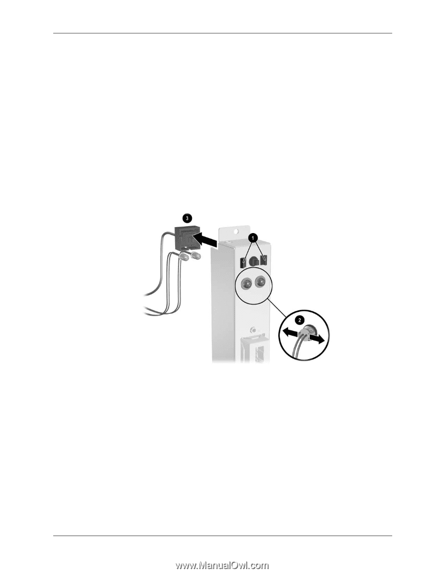
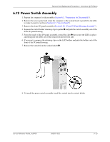
Removal and Replacement Procedures- Microtower (µT) Chassis 6.12 Power Switch Assembly 1. Prepare the computer for disassembly (Section 6.1, "Preparation for Disassembly"). 2. Remove the access panel and rotate the computer so the system board is parallel to the table to make it easier to work on (Section 6.3, "Access Panel"). 3. Remove the front I/O panel assembly (Section 6.10, "Front I/O Panel Housing Assembly"). 4. Squeeze the switch holder retaining clips together 1 and push the switch assembly out of the front I/O panel housing. 5. From the inside of the I/O panel assembly, spread the clips 2 that secure the LEDs in place and then push the LEDs out of the retainers from the front side. 6. If necessary, compress the retaining clips on the LED holders and push the holders out of the front of the I/O panel housing. 7. Remove the switch from the switch holder 3. 8. To install the power switch assembly install the switch into the switch holder. Service Reference Guide, dc5000 360201-002 6-23
-
 1
1 -
2
-
3
-
4
-
5
-
6
-
7
-
8
-
9
-
10
-
11
-
12
-
13
-
14
-
15
-
16
-
17
-
18
-
19
-
20
-
21
-
22
-
23
-
24
-
25
-
26
-
27
-
28
-
29
-
30
-
31
-
32
-
33
-
34
-
35
-
36
-
37
-
38
-
39
-
40
-
41
-
42
-
43
-
44
-
45
-
46
-
47
-
48
-
49
-
50
-
51
-
52
-
53
-
54
-
55
-
56
-
57
-
58
-
59
-
60
-
61
-
62
-
63
-
64
-
65
-
66
-
67
-
68
-
69
-
70
-
71
-
72
-
73
-
74
-
75
-
76
-
77
-
78
-
79
-
 80
80 -
 81
81 -
 82
82 -
 83
83 -
 84
84 -
 85
85 -
 86
86 -
 87
87 -
 88
88 -
 89
89 -
 90
90 -
91
-
92
-
93
-
94
-
95
-
96
-
97
-
98
-
99
-
100
-
101
-
102
-
103
-
104
-
105
-
106
-
107
-
108
-
109
-
110
-
111
-
112
-
113
-
114
-
115
-
116
-
117
-
118
-
119
-
120
-
121
-
122
-
123
-
124
-
125
-
126
-
127
-
128
-
129
-
130
-
131
-
132
-
133
-
134
-
135
-
136
-
137
-
138
-
139
-
140
-
141
-
142
-
143
-
144
-
145
-
146
-
147
-
148
-
149
-
150
-
151
-
152
-
153
-
154
-
155
-
156
-
157
-
158
-
159
-
160
-
161
-
162
-
163
-
164
-
165
-
166
-
167
-
168
-
169
-
170
-
171
-
172
-
173
-
174
-
175
-
176
-
177
-
178
-
179
-
180
 |
 |