HP LaserJet Enterprise 500 Service Manual
HP LaserJet Enterprise 500 Manual
 |
View all HP LaserJet Enterprise 500 manuals
Add to My Manuals
Save this manual to your list of manuals |
HP LaserJet Enterprise 500 manual content summary:
- HP LaserJet Enterprise 500 | Service Manual - Page 1
LASERJET ENTERPRISE 500 COLOR Service Manual M551n M551dn M551xh - HP LaserJet Enterprise 500 | Service Manual - Page 2
- HP LaserJet Enterprise 500 | Service Manual - Page 3
HP LaserJet Enterprise 500 color M551 Printers Service Manual - HP LaserJet Enterprise 500 | Service Manual - Page 4
contained herein is subject to change without notice. The only warranties for HP products and services are set forth in the express warranty statements accompanying such products and services. Nothing herein should be construed as constituting an additional warranty. HP shall not be liable - HP LaserJet Enterprise 500 | Service Manual - Page 5
Conventions used in this guide TIP: Tips provide helpful hints or shortcuts. NOTE: Notes provide important information to explain a concept or to complete a task. CAUTION: Cautions indicate procedures that you - HP LaserJet Enterprise 500 | Service Manual - Page 6
iv Conventions used in this guide ENWW - HP LaserJet Enterprise 500 | Service Manual - Page 7
Table of contents 1 Theory of operation ...1 Basic operation ...2 Sequence of operation 3 Engine control system ...4 DC controller ...5 Solenoids 6 Clutches ...6 Switches 6 Sensors ...7 Motors and fans 7 High voltage power supply 10 Low voltage power supply 12 Overcurrent/overvoltage - HP LaserJet Enterprise 500 | Service Manual - Page 8
and disengagement 29 Intermediate transfer belt (ITB) unit 31 Primary-transfer-roller engagement and disengagement 32 ITB cleaning 35 Calibration ...36 Color misregistration control 36 Image stabilization control 37 Pickup, feed, and delivery system 38 Pickup-and-feed unit 42 Cassette pickup - HP LaserJet Enterprise 500 | Service Manual - Page 9
Required tools ...72 Service approach ...73 Before performing service 73 After performing service 73 Post service test ...73 Print-quality test 73 Parts removal order 74 Customer self repair (CSR) components 76 Print cartridges ...76 Duplex reverse guide 78 Toner collection unit 79 Formatter - HP LaserJet Enterprise 500 | Service Manual - Page 10
the residual toner collection door 142 Registration density (RD) sensor assembly 143 Remove the RD sensor assembly 143 Power supply fan and fan duct 147 Remove the power supply fan and fan duct 147 Registration assembly 150 Remove the registration assembly 150 Lower pickup guide 155 Remove - HP LaserJet Enterprise 500 | Service Manual - Page 11
Reinstall the high voltage power supply lower 169 Developing disengagement motor 170 Remove the developing disengagement motor 170 Pickup motor ...172 Remove the pickup motor 172 Lifter drive assembly 173 Remove the lifter drive assembly 173 Automatic close assembly 175 Remove the automatic - HP LaserJet Enterprise 500 | Service Manual - Page 12
Troubleshooting process ...243 Determine the problem source 243 Troubleshooting flowchart 243 Power subsystem 244 Power-on checks 244 Power-on troubleshooting overview 244 Tools for troubleshooting front-door interlock switches 269 Tray/bin manual sensor test 271 Print/stop test 279 - HP LaserJet Enterprise 500 | Service Manual - Page 13
x 500 paper feeder 293 General timing chart 294 Circuit diagrams 295 Internal print-quality test pages 297 Print quality troubleshooting pages 297 important information on the configuration pages 306 Color band test 307 Print quality troubleshooting tools 308 Repetitive defects ruler 308 - HP LaserJet Enterprise 500 | Service Manual - Page 14
Unsupported supply in use 396 10.XX.70 Printing past very low 396 10.YY.15 Install - HP LaserJet Enterprise 500 | Service Manual - Page 15
.XX 417 47.02.XX 417 47.03.XX 418 47.04.XX 418 47.05.00 418 47.06.XX 418 47.WX.YZ Printer calibration error To continue, press OK 418 49.XX.YY To continue, turn off then on 420 50.WX.YZ Fuser error To continue, turn - HP LaserJet Enterprise 500 | Service Manual - Page 16
99.00.07 Upgrade not performed error reading upgrade 435 99.00.08 Upgrade not performed error reading upgrade 435 99.00.09 Upgrade canceled by user 435 99.00.10 Upgrade canceled by user 436 99.00.11 Upgrade canceled by user 436 99.00.12 Upgrade not performed the file is invalid 436 99.00.13 - HP LaserJet Enterprise 500 | Service Manual - Page 17
stack Then press OK to print second sides 452 Manually feed: [Type], [Size 452 Manually feed: [Type], [Size] To use another tray, press OK 452 Moving solenoid 452 Moving solenoid and motor 453 No job to cancel 453 Paused 453 Performing Color Band Test 453 Performing Paper Path Test 453 - HP LaserJet Enterprise 500 | Service Manual - Page 18
461 Restricted from printing in color 461 Rotating motor 461 Rotating motor 461 Size mismatch in Tray - HP LaserJet Enterprise 500 | Service Manual - Page 19
500- problems 492 Product feeds multiple sheets 492 Paper does not feed automatically 492 Use manual print modes ...494 Solve image quality problems problems 504 Solve connectivity problems 505 Solve direct connect problems 505 Solve network problems 505 Service mode functions ...507 Service - HP LaserJet Enterprise 500 | Service Manual - Page 20
toner collection unit 527 Memory ...527 Customer self repair (CSR) and service 500-sheet paper feeder 552 Paper feeder covers 554 Paper feeder main body 556 Paper feeder cassette 558 Paper feeder PCA 560 Alphabetical parts list ...562 Numerical parts list ...568 Appendix A Service and support - HP LaserJet Enterprise 500 | Service Manual - Page 21
warranty statement 578 Color LaserJet Fuser Kit, Toner Collection Unit, and Transfer Kit Limited Warranty Statement .......... 579 Data stored on the print cartridge 580 End User License Agreement 581 OpenSSL ...584 Customer self-repair warranty service 585 Customer support ...586 Appendix - HP LaserJet Enterprise 500 | Service Manual - Page 22
Laser safety ...598 Canadian DOC regulations 598 VCCI statement (Japan 598 Power cord instructions 598 Power cord statement (Japan 598 EMC statement (Korea 599 Laser statement for Finland 599 GS statement (Germany 600 Substances Table (China 600 Restriction on - HP LaserJet Enterprise 500 | Service Manual - Page 23
1-19 Paper size detection ...62 Table 3-1 Troubleshooting flowchart ...243 Table 3-2 Heartbeat LED, product Manual sensor test 2 diagnostic tests 271 Table 3-9 Component test details ...280 Table 3-10 Sensors ...282 Table 3-11 DC controller connectors 284 Table 3-12 Paper feeder driver - HP LaserJet Enterprise 500 | Service Manual - Page 24
menu 365 Table 3-29 Jetdirect Menu ...365 Table 3-30 Troubleshooting menu 382 Table 3-31 Backup/Restore menu 388 Table 3-32 Optimize submenu 495 Table 3-49 Image defects table ...497 Table 3-50 Solve performance problems 504 Table 3-51 Preboot menu options (1 of 5 514 Table 3-52 Preboot - HP LaserJet Enterprise 500 | Service Manual - Page 25
(4 of 5 543 Table 4-8 Internal assemblies (5 of 5 545 Table 4-9 Cassette ...547 Table 4-10 Paper pickup assembly ...549 Table 4-11 PCAs ...551 Table 4-12 1 x 500-sheet paper feeder 553 Table 4-13 Paper feeder covers ...555 Table 4-14 Paper feeder main body ...557 Table 4-15 Cassette ...559 Table - HP LaserJet Enterprise 500 | Service Manual - Page 26
xxiv ENWW - HP LaserJet Enterprise 500 | Service Manual - Page 27
23 ITB unit ...31 Figure 1-24 Three states of primary-transfer-roller engagement and disengagement 33 Figure 1-25 ITB cleaning process ...35 Figure 1-26 Toner patterns for calibration 36 Figure 1-27 Switches and sensors for the pickup, feed, and delivery system (1 of 2 38 Figure 1-28 Switches and - HP LaserJet Enterprise 500 | Service Manual - Page 28
of 2 77 Figure 2-6 Remove the duplex reverse guide (1 of 2 78 Figure 2-7 Remove the duplex reverse guide (2 of 2 78 Figure 2-8 Remove the toner collection unit (1 of 4 79 Figure 2-9 Remove the toner collection unit (2 of 4 79 Figure 2-10 Remove the toner collection unit (3 of 4 80 Figure 2-11 - HP LaserJet Enterprise 500 | Service Manual - Page 29
Figure 2-22 Remove the pickup roller (Tray 1; 2 of 2 88 Figure 2-23 Remove the pickup roller (Tray 2; 1 of 4 89 Figure 2-24 Remove the pickup roller (Tray 2; 2 of 4 89 Figure 2-25 Remove the pickup roller (Tray 2; 3 of 4 90 Figure 2-26 Remove the pickup roller (Tray 2; 4 of 4 90 Figure 2-27 - HP LaserJet Enterprise 500 | Service Manual - Page 30
and environmental sensor (9 of 9 135 Figure 2-95 Remove the toner collection sensor (1 of 4 136 Figure 2-96 Remove the toner collection sensor (2 of 4 136 Figure 2-97 Remove the toner collection sensor (3 of 4 137 Figure 2-98 Remove the toner collection sensor (4 of 4 137 Figure 2-99 Remove the - HP LaserJet Enterprise 500 | Service Manual - Page 31
feed motor (6 of 7 141 Figure 2-105 Remove the residual toner feed motor (7 of 7 141 Figure 2-106 Reinstall the residual toner collection door 142 Figure 2-107 Remove the RD sensor assembly (1 of 6 143 Figure 2-108 Remove the RD sensor assembly (2 of 6 144 Figure 2-109 Remove the - HP LaserJet Enterprise 500 | Service Manual - Page 32
Figure 2-145 Remove the developing disengagement motor (2 of 2 171 Figure 2-146 Remove the pickup motor 172 Figure 2-147 Remove the lifter drive assembly (1 of 2 173 Figure 2-148 Remove the lifter drive assembly (2 of 2 174 Figure 2-149 Remove the automatic close assembly 175 Figure 2-150 - HP LaserJet Enterprise 500 | Service Manual - Page 33
Figure 2-186 Reinstall the PGC actuators (2 of 5 199 Figure 2-187 Reinstall the PGC actuators (3 of 5 199 Figure 2-188 Reinstall the PGC actuators (4 of 5 200 Figure 2-189 Reinstall the PGC actuators (5 of 5 200 Figure 2-190 Remove the high voltage power supply upper (1 of 5 202 Figure 2-191 - HP LaserJet Enterprise 500 | Service Manual - Page 34
27 Test the optional Tray 3 media size sensors 279 Figure 3-28 Sensors ...282 Figure 3-29 DC controller PCA ...284 Figure 3-30 Paper feeder driver PCA 285 Figure 3-31 Component locations (1 of 6 286 Figure 3-32 Component locations (2 of 6 287 Figure 3-33 Component locations (3 of 6 288 Figure - HP LaserJet Enterprise 500 | Service Manual - Page 35
3-36 Component locations (6 of 6 291 Figure 3-37 1 x 500 paper feeder ...293 Figure 3-38 General timing chart ...294 Figure 3-39 General circuit diagram 295 Figure 3-40 Paper feeder circuit diagram 296 Figure 3-41 Print-quality troubleshooting procedure 297 Figure 3-42 Yellow print-quality - HP LaserJet Enterprise 500 | Service Manual - Page 36
xxxiv ENWW - HP LaserJet Enterprise 500 | Service Manual - Page 37
1 Theory of operation ● Basic operation ● Engine control system ● Laser/scanner system ● Image formation system ● Pickup, feed, and delivery system ● Jam detection ● Optional paper feeder ENWW 1 - HP LaserJet Enterprise 500 | Service Manual - Page 38
circuit assembly (PCA) ● The laser/scanner system, which forms the latent image on the photosensitive drum ● The image-formation system, which transfers a toner image onto the paper ● The media feed system, which uses a system of rollers and belts to transport the paper through the product ● Option - HP LaserJet Enterprise 500 | Service Manual - Page 39
the image on the enters the paper path until the last sheet photosensitive drums has passed through the fuser ● Transfers the toner to the paper ● Fuses the toner image onto the paper ● Performs calibration after a specified number of pages Last rotation From the time the last sheet of paper - HP LaserJet Enterprise 500 | Service Manual - Page 40
Engine control system The engine-control system receives commands from the formatter and interacts with the other main systems to coordinate all product functions. The engine-control system consists of the following components: ● DC controller ● High-voltage power supply ● Low-voltage power supply - HP LaserJet Enterprise 500 | Service Manual - Page 41
DC controller The DC controller controls the operational sequence of the printer. Figure 1-3 DC controller block diagram Fuser Laser/scanner ENWW Engine control system 5 - HP LaserJet Enterprise 500 | Service Manual - Page 42
solenoid Clutches Table 1-3 Clutches Component abbreviation Component name CL1 Duplex re-pickup clutch (HP LaserJet Enterprise 500 color M551dn and HP LaserJet Enterprise 500 color M551xh only) Switches Table 1-4 Switches Component abbreviation Component name SW1, SW2 5V interlock switch - HP LaserJet Enterprise 500 | Service Manual - Page 43
sensor (HP LaserJet Enterprise 500 color M551dn and HP LaserJet Enterprise 500 color M551xh only) OHT sensor (in) OHT sensor (out) RD sensor (front) RD sensor (rear) Environmental sensor (temperature and humidity) Yellow toner-level sensor Magenta toner-level sensor Cyan toner-level sensor - HP LaserJet Enterprise 500 | Service Manual - Page 44
Developing disengagement motor Drives the developing unit disengagement Stepping motor M11 Duplex reverse motor (HP LaserJet Enterprise 500 color M551dn and HP LaserJet Enterprise 500 color M551xh only) Drives the duplex reverse roller and duplex feed roller Stepping motor Failure detection - HP LaserJet Enterprise 500 | Service Manual - Page 45
-feed motor M13 Pickup motor Purpose Drives the residual toner feed screw Drives the cassette pickup roller, MP tray pickup roller, feed roller, registration roller, and re-pickup roller Type DC motor Stepping motor Failure - HP LaserJet Enterprise 500 | Service Manual - Page 46
High voltage power supply The high-voltage power supply delivers the high-voltage biases to the following components used to transfer toner during the image-formation process: ● Primary-charging roller (in the cartridge) ● Developing roller (in the cartridge) ● Primary-transfer roller ● Secondary- - HP LaserJet Enterprise 500 | Service Manual - Page 47
Table 1-8 High voltage power supply circuits (continued) Circuit Description Primary-transfer-bias generation DC positive bias transfers the latent toner image from each photosensitive drum onto the ITB. Secondary-transfer-bias generation Two DC biases, one positive and one negative, transfer - HP LaserJet Enterprise 500 | Service Manual - Page 48
Low voltage power supply The low-voltage power-supply circuit converts the AC power from the wall receptacle into the DC voltage that the product components use. The product has two low-voltage power-supplies for 110 Volt or 220 Volt input. Figure 1-5 Low voltage power-supply circuit AC input Fuse - HP LaserJet Enterprise 500 | Service Manual - Page 49
Table 1-9 Converted DC voltages Main DC voltage Sub-voltage +24 V +24VA +24VB +5 V +5VA +5VB +3.3 V +5VC +5VD 3.3VA 3.3VB 3.3VC Behavior Notes Stopped during Sleep (powersave) mode The 24V POWER SUPPLY (24VRMT) signal controls supply or interruption of +24VA. Interrupted when the front - HP LaserJet Enterprise 500 | Service Manual - Page 50
Overcurrent/overvoltage protection The low-voltage power supply stops supplying the DC voltage to the product components whenever it detects excessive current or abnormal voltage from the power source. The low-voltage power supply has a protective circuit against overcurrent and overvoltage to - HP LaserJet Enterprise 500 | Service Manual - Page 51
Power off condition The DC controller turns off the product with the 24V POWER SUPPLY (24VRMT) signal, 5V POWER SUPPLY (VC5VOFF) signal, 3V POWER SUPPLY (VC3VOFF) signal, and VOLTAGE CONVERSION (PWRSAVE) signal. +5VA and +5VC, are converted into +3.2V, and +3.3VA and supplied during the power off - HP LaserJet Enterprise 500 | Service Manual - Page 52
Fuser temperature control circuit The temperatures of the two rollers in the fuser fluctuate according to the stage of the printing process. The DC controller sends commands to the fuser-control circuit to adjust temperatures. Figure 1-7 Fuser temperature control circuit Fuser Fuser sleeve unit - HP LaserJet Enterprise 500 | Service Manual - Page 53
excessive temperatures, the product has four layers of protective functions. If one function fails, the subsequent functions should detect the problem. ● DC controller: When a thermistor or thermopile detects a temperature above a certain threshold, the DC controller interrupts power to the specific - HP LaserJet Enterprise 500 | Service Manual - Page 54
circuit failure: The DC controller determines a drive-circuit failure: ◦ If the detected power supply frequency is out of a specified range when the printer is turned on or during the standby period ◦ If the current detection circuit detects an out of specified current value ● Fuser discrepancy: The - HP LaserJet Enterprise 500 | Service Manual - Page 55
for yellow and magenta and the other for cyan and black. The formatter sends the DC controller instructions for the image of the page to be printed. The DC controller signals the lasers to emit surface of the drum so it can receive toner. Figure 1-8 Laser/scanner system ENWW Laser/scanner system 19 - HP LaserJet Enterprise 500 | Service Manual - Page 56
The DC controller determines that a laser/scanner has failed when any of the following conditions occurs: ● Laser failure: The detected laser intensity does not match a specified value when the product initializes. ● Beam-detect (BD) failure: The BD interval is outside a specified range during - HP LaserJet Enterprise 500 | Service Manual - Page 57
Image formation system The image-formation system creates the printed image on the paper. The system consists of the laser/ scanners, print cartridges, imaging drums, ITB, and fuser. Figure 1-9 Image formation system Fuser Y M C K Laser/scanner Laser/scanner ENWW Image formation system 21 - HP LaserJet Enterprise 500 | Service Manual - Page 58
to the electrostatic latent image on the photosensitive drums. The toner image transfers to the ITB and subsequently to the paper. The toner fuses to the paper to make a permanent image. Residual toner is removed from the ITB. Residual toner is removed from the photosensitive drums. 22 Chapter - HP LaserJet Enterprise 500 | Service Manual - Page 59
Step 1: Pre-exposure Light from the pre-exposure LED strikes the surface of the photosensitive drum to remove any residual electrical charges from the drum surface. Figure 1-11 Pre-exposure Step 2: Primary charging The primary-charging roller contacts the photosensitive drum and charges the drum - HP LaserJet Enterprise 500 | Service Manual - Page 60
developing blade. Because the negatively charged surface of the photosensitive drums have been neutralized where they have been struck by the laser beam, the toner adheres to those areas on the drums. The latent image becomes visible on the surface of each drum. Figure 1-14 Development 24 Chapter - HP LaserJet Enterprise 500 | Service Manual - Page 61
primary-transfer rollers contact the ITB, giving the ITB a positive charge. The ITB attracts the negatively charged toner from the surface of each photosensitive drum, and the complete toner image transfers onto the ITB, beginning with yellow, followed by magenta, cyan, and black. Figure 1-15 - HP LaserJet Enterprise 500 | Service Manual - Page 62
causes it to separate from the ITB as the ITB bends. The static-charge eliminator removes excess charge from the paper to ensure that the toner fuses correctly. Figure 1-17 Separation Step 8: Fusing To create the permanent image, the paper passes through heated, pressurized rollers to melt the - HP LaserJet Enterprise 500 | Service Manual - Page 63
print cartridge. Figure 1-20 Drum cleaning Print cartridge The product has four print cartridges, one for each color. Each print cartridge contains a reservoir of toner and the following components: ● Photosensitive drum ● Developing roller ● Primary-charging roller ENWW Image formation system 27 - HP LaserJet Enterprise 500 | Service Manual - Page 64
The DC controller rotates the drum motor to drive the photosensitive drum, developing roller, and the primary-charging roller. Figure 1-21 Print-cartridge system The DC controller rotates the drum motor to drive the photosensitive drum, developing unit, and primary charging roller. The memory tag - HP LaserJet Enterprise 500 | Service Manual - Page 65
. ● The toner level in any of the print cartridges drops below a certain level Developing roller engagement and disengagement The product can print in full-color mode or in black-only mode. To print in black-only mode, the product disengages the developing rollers in the cyan, magenta, and yellow - HP LaserJet Enterprise 500 | Service Manual - Page 66
and changes the direction of the cam according to the instructions from the formatter for each print job. When the product the developing rollers disengage from the photosensitive drums. If the next print job is full-color mode, each of the developing rollers engage. If the next print job is black - HP LaserJet Enterprise 500 | Service Manual - Page 67
Intermediate transfer belt (ITB) unit The ITB unit accepts the toner images from the photosensitive drums and transfers the completed image to the paper. The ITB unit has these main components: ● ITB ● ITB drive roller ● ITB- - HP LaserJet Enterprise 500 | Service Manual - Page 68
and disengagement Depending on the requirements of the print job, the primary-transfer rollers engage with the ITB so it can receive toner from the photosensitive drums. Table 1-12 Primary-transfer-roller engagement states Roller state Product state All rollers disengaged The home position for - HP LaserJet Enterprise 500 | Service Manual - Page 69
Table 1-12 Primary-transfer-roller engagement states (continued) Roller state Product state All rollers engaged The state for a full-color print job Black roller engaged The state for a black-only print job Figure 1-24 Three states of primary-transfer-roller engagement and disengagement - HP LaserJet Enterprise 500 | Service Manual - Page 70
If the DC controller does not receive the expected signal from the ITB home-position sensor when the primary-transfer-roller engages or disengages, but the primary-transfer-roller disengagement motor is rotating, the DC controller determines that the primary-transfer-disengagement mechanism has - HP LaserJet Enterprise 500 | Service Manual - Page 71
motor (M5) drives the residual toner feed screw. The screw feeds the residual toner to the residual toner feed unit. The residual toner feed motor (M12) drives the residual toner feed screw. The residual toner feed screw deposits the residual toner in the toner collection box. The DC control detects - HP LaserJet Enterprise 500 | Service Manual - Page 72
if adjustments are necessary. Figure 1-26 Toner patterns for calibration Color misregistration control Internal variations in the laser/scanners can cause the toner images to become misaligned. The colormisregistration control corrects the following problems: ● Horizontal scanning start position - HP LaserJet Enterprise 500 | Service Manual - Page 73
related to deterioration of the photosensitive drum or the toner. The DC controller adjusts the high-voltage biases to correct the problem under the following conditions: ● The sub thermistor the product is turned on or when the color misregistration control starts. ENWW Image formation system 37 - HP LaserJet Enterprise 500 | Service Manual - Page 74
Pickup, feed, and delivery system The pickup, feed, and delivery system uses a series of rollers to move the paper through the product. Figure 1-27 Switches and sensors for the pickup, feed, and delivery system (1 of 2) Y M C K Table 1-14 Switches - HP LaserJet Enterprise 500 | Service Manual - Page 75
Table 1-14 Switches and sensors for the pickup, feed, and delivery system (1 of 2) (continued) Abbreviation Component SR21 Tray 1 paper SR22 Duplexer refeed (duplex models only) Figure 1-28 Switches and sensors for the pickup, feed, and delivery system (2 of 2) SR10 Table 1-15 Switches and - HP LaserJet Enterprise 500 | Service Manual - Page 76
Figure 1-29 Motors and solenoids for the pickup, feed, and delivery system Y M C K Table 1-16 Motors and solenoids for the pickup, feed, and delivery system Abbreviation Component M2 Fuser motor M5 Drum motor 3 M7 Lifter motor M11 Duplex reverse motor (duplex models only) M13 Pickup - HP LaserJet Enterprise 500 | Service Manual - Page 77
Figure 1-30 Three main units of the pickup, feed, and delivery system Fuser/delivery block Duplex block Y M C K ENWW Pickup, feed, and delivery system 41 - HP LaserJet Enterprise 500 | Service Manual - Page 78
Pickup-and-feed unit The pickup-and-feed unit picks an individual sheet of paper from the multipurpose tray or the cassettes, carries it through the secondary-transfer unit, and feeds it into the fuser. Figure 1-31 Pick feed mechanism Y M C K 42 Chapter 1 Theory of operation ENWW - HP LaserJet Enterprise 500 | Service Manual - Page 79
mechanism NOTE: The lift-up operation lifts the lifting plate to keep the stack surface of the media at a pickup position. The lifting spring helps support the lifting plate depending on the media size and amount. ENWW Pickup, feed, and delivery system 43 - HP LaserJet Enterprise 500 | Service Manual - Page 80
Cassette presence detection The cassette presence sensor is in the lifter drive unit. The sensor detects the cassette-presence sensor flag and determines whether the cassette is installed correctly. Figure 1-33 Cassette presence sensor 44 Chapter 1 Theory of operation ENWW - HP LaserJet Enterprise 500 | Service Manual - Page 81
to the position where the media can be picked up. The lift operation is performed by monitoring the cassette media-stack-surface sensor when the printer is turned on, when the cassette is installed, or as needed during a print operation. If the paper-stack surface sensor does not detect the paper - HP LaserJet Enterprise 500 | Service Manual - Page 82
Cassette paper presence detection The cassette media-presence sensor detects whether paper is in the cassette. Figure 1-35 Paper level detection mechanism 46 Chapter 1 Theory of operation ENWW - HP LaserJet Enterprise 500 | Service Manual - Page 83
The DC controller determines the paper size using the paper-width sensor. The paper-width sensor flag moves relative to the cassette-side paper guide. The pickup pressure is adjusted according to the paper size to prevent a pickup failure. The pickup pressure increases when large paper sizes (Letter - HP LaserJet Enterprise 500 | Service Manual - Page 84
separation roller. Therefore, the separation roller holds back any multiple-fed sheets, and one sheet of media is fed into the printer. Figure 1-37 Multifeed prevention Cassette pickup roller Cassette separation roller Media Lifting plate Normal feed Separation roller does not rotate Multiple - HP LaserJet Enterprise 500 | Service Manual - Page 85
Multipurpose tray pickup The multipurpose tray paper-presence sensor detects whether paper is in the tray. If no paper is present, the DC controller notifies the formatter. Printing does not occur until paper is in the tray. The sequence of steps for the multipurpose tray pickup operation as follows - HP LaserJet Enterprise 500 | Service Manual - Page 86
the leading edge of image on the ITB. 3. The DC controller detects whether or not the media is overhead transparency, using the OHT sensor. 4. The toner image on the ITB transfers onto the media, which feeds to the fuser. Figure 1-39 Paper-feed mechanism 50 Chapter 1 Theory of operation ENWW - HP LaserJet Enterprise 500 | Service Manual - Page 87
Skew-feed prevention The product can straighten the paper without slowing the feed operation. 1. As the paper enters the paper path, the leading edge strikes the registration shutter, which straightens the paper. The paper does not pass through the shutter . 2. The feed rollers keep pushing the - HP LaserJet Enterprise 500 | Service Manual - Page 88
the specified value, the DC controller determines that the OHT sensor has failed. Fusing and delivery unit The fusing and delivery unit fuses the toner onto the paper and delivers the printed page into the output bin. The following controls ensure optimum print quality: ● Loop control ● Pressure - HP LaserJet Enterprise 500 | Service Manual - Page 89
fuser rollers rotate faster than the secondary transfer rollers, the paper warp decreases and the toner image fails to transfer to the paper correctly, causing color misregistration. To prevent these problems, the loop sensors, which are located between the secondary transfer rollers and the fuser - HP LaserJet Enterprise 500 | Service Manual - Page 90
Pressure-roller pressurization control To prevent excessive wear on the pressure roller and help with jam-clearing procedures, the pressure roller pressurizes only during printing and standby. The DC controller reverses the fuser motor. The fuser motor rotates the fuser pressure-release cam. Figure - HP LaserJet Enterprise 500 | Service Manual - Page 91
Duplexing unit (duplex models) For supported models, the duplexing unit reverses the paper and feeds it through the paper path to print the second side. The duplexing unit consists of the - HP LaserJet Enterprise 500 | Service Manual - Page 92
-feed unit. 3. The duplexing re-pickup motor and duplexing feed motor move the paper into the duplexing repickup unit. 4. To align the paper with the toner image on the ITB, the duplexing re-pickup motor stops and the paper pauses. 5. The paper re-enters the paper path, and the second side - HP LaserJet Enterprise 500 | Service Manual - Page 93
Jam detection The product uses the following sensors to detect the paper as it moves through the paper path and to report to the DC controller if the paper has jammed. ● Fuser output sensor (SR5) ● Registration sensor (SR8) ● Fuser loop 1 (SR14) ● Fuser loop 2 (SR15) ● Duplexer refeed (SR22) Figure - HP LaserJet Enterprise 500 | Service Manual - Page 94
Table 1-17 Jams that the product detects (continued) Jam Description Fuser delivery delay jam The fuser delivery paper-feed sensor does not detect the leading edge of the paper within a specified period after the TOP sensor detects the leading edge. Fuser delivery stationary jam The fuser - HP LaserJet Enterprise 500 | Service Manual - Page 95
print media and feeds it to the printer. NOTE: These optional trays are not identical to the main cassette (Tray 2). Figure 1-46 Optional paper feeder Y M C K The paper-deck drivers contain a microcomputer and control the paper feeder. The paper-deck drivers receive commands from the DC controller - HP LaserJet Enterprise 500 | Service Manual - Page 96
Figure 1-47 Signals for the paper feeder The input trays contain several motors, solenoids, sensors, and switches, as described in the following table. Table 1-18 Electrical components for the paper feeder Component type Abbreviation Component name Motors M1 Paper feeder motor M2 Paper - HP LaserJet Enterprise 500 | Service Manual - Page 97
Paper-feeder pickup and feed operation The paper feeder picks up one sheet from the paper-feeder cassette and feeds it to the product. Figure 1-48 Paper-feeder pickup and feed operation ENWW Optional paper feeder 61 - HP LaserJet Enterprise 500 | Service Manual - Page 98
detection The paper-feeder cassette media-size switch (SW1) detects the size of paper loaded in the paper-feeder cassette. The paper-feeder driver determines the media size by monitoring the combination of the switches. Figure 1-49 Paper size detection Table 1-19 Paper size detection Paper size - HP LaserJet Enterprise 500 | Service Manual - Page 99
size switch (SW1) detects whether the paper-feeder cassette is installed correctly. The paper-feeder driver determines if a cassette is absent when all three switches are turned off. The paper-feeder driver determines a cassette presence when one of the switches is turned on. ENWW Optional paper - HP LaserJet Enterprise 500 | Service Manual - Page 100
on, when the printer recovers from sleep mode and when the paper-feeder cassette is installed. The operational sequence of the lift operation is as follows: 1. The paper-feeder driver rotates the paper-feeder lifter motor to lift the lifting plate. 2. The paper-feeder driver stops the paper-feeder - HP LaserJet Enterprise 500 | Service Manual - Page 101
The paper-feeder driver notifies the formatter if either of the paper-feeder media-stack surface sensors fails to detect the stack surface within a specified period from when a lift-up operation starts. ENWW Optional paper feeder 65 - HP LaserJet Enterprise 500 | Service Manual - Page 102
Paper feeder presence detection The Tray 3 paper present (SR3) detects whether the paper is present in the paper-feeder cassette. 66 Chapter 1 Theory of operation ENWW - HP LaserJet Enterprise 500 | Service Manual - Page 103
feeder separation roller, and pushes the extra sheets back to the paper-feeder cassette. That way, only the top sheet is fed to the printer. Figure 1-51 Paper-feeder multiple feed prevention No-load Normal feed Multiple-feed ENWW Rotational force for paper-feeder separation roller: Pushes back the - HP LaserJet Enterprise 500 | Service Manual - Page 104
to check whether paper has jammed. Figure 1-52 Jam detection Y M C K The paper-feeder driver identifies a jam if the sensor detects paper at a specified timing stored in the paper-feeder driver. The paper-feeder driver stops printing and notifies the formatter through the DC controller of the jam - HP LaserJet Enterprise 500 | Service Manual - Page 105
2 Removal and replacement ● Introduction ● Removal and replacement strategy ● Service approach ● Customer self repair (CSR) components ● Covers ● Internal assemblies ● Optional paper feeder assembly (Tray 3) ENWW 69 - HP LaserJet Enterprise 500 | Service Manual - Page 106
support repairing individual subassemblies or troubleshooting to the component level. Note the length, diameter, color lance points, or wire-harness guides and retainers. Removal and replacement troubleshooting. However, disconnect the power supply during parts removal. Never operate or service - HP LaserJet Enterprise 500 | Service Manual - Page 107
Electrostatic discharge CAUTION: Some parts are sensitive to electrostatic discharge (ESD). Look for the ESD reminder when removing product parts. Always perform service work at an ESD protected workstation or mat, or use an ESD strap. If an ESD workstation, mat, or strap is not available, ground - HP LaserJet Enterprise 500 | Service Manual - Page 108
Required tools ● #2 Phillips screwdriver with a magnetic tip and a 152-mm (6-inch) shaft length ● Small flat blade screwdriver ● Needle-nose pliers ● ESD mat or ESD strap (if one is available) ● Penlight (optional) CAUTION: Always use a Phillips screwdriver (callout 1). Do not use a pozidrive - HP LaserJet Enterprise 500 | Service Manual - Page 109
the print cartridges. ● Reinstall the tray cassette or cassettes. ● If the 1 x 500-sheet paper feeder was removed for service, place the product on the feeder. Engage the feeder tray locks to secure the feeder to the product. Post service test Perform the following test to verify that the repair or - HP LaserJet Enterprise 500 | Service Manual - Page 110
Parts removal order Figure 2-2 Parts removal order (1 of 2) Component Remove Remove Remove Remove Print cartridges Duplex reverse guide Toner collection unit (TCU) Formatter Hard drive (HDD) Formatter Solid state drive Formatter (SSD) Memory DIMMs Formatter Tray 2-3 cassettes Fuser Tray - HP LaserJet Enterprise 500 | Service Manual - Page 111
of 2) Component Remove Delivery fan, cartridge fan, and TCU environmental sensor Toner collection TCU sensor Residual-toner feed motor TCU Registration density (RD) T2 sensor Power supply (PS) Delivery assembly RD sensor Cassette pickup drive assembly ENWW Service approach 75 - HP LaserJet Enterprise 500 | Service Manual - Page 112
Customer self repair (CSR) components Print cartridges CAUTION: If toner gets on your clothing, wipe it off with a dry cloth and wash clothing in cold water. Hot water sets toner into fabric. 1. Open the front door. Make sure that the door is completely open. Figure 2-4 Remove the print cartridge (1 - HP LaserJet Enterprise 500 | Service Manual - Page 113
2. Grasp the print-cartridge handle and pull out to remove. Repeat this step for each print cartridge. CAUTION: Do not touch the green roller. Doing so can damage the cartridge. Do not expose the cartridge to strong light. Cover the cartridge with a sheet of paper to protect it from light. - HP LaserJet Enterprise 500 | Service Manual - Page 114
Duplex reverse guide 1. Grasp the duplex reverse guide and pull it away from the product to release it. Figure 2-6 Remove the duplex reverse guide (1 of 2) 2. Remove the guide. Figure 2-7 Remove the duplex reverse guide (2 of 2) 78 Chapter 2 Removal and replacement ENWW - HP LaserJet Enterprise 500 | Service Manual - Page 115
is designed for a single use. Do not try to empty the toner collection unit and reuse it. Doing so could cause toner to spill inside the product and result in reduced print quality. For recycling information, see the product user guide. 1. Open the front door. Make sure that the door is completely - HP LaserJet Enterprise 500 | Service Manual - Page 116
3. To prevent toner spills, place the blue cap (callout 1) over the blue opening at the top of the unit (callout 2). Figure 2-10 Remove the toner collection unit (3 of 4) 2 1 Figure 2-11 Remove the toner collection unit (4 of 4) 4. Recycle the toner collection unit. 80 Chapter 2 Removal and - HP LaserJet Enterprise 500 | Service Manual - Page 117
Formatter PCA CAUTION: ESD sensitive component. 1. Turn the product off and disconnect the power and interface cable or interface cables. 2. Unscrew the formatter thumb screws, and then firmly pull the formatter from the product. Place the formatter on a clean, flat, grounded surface. Figure 2-12 - HP LaserJet Enterprise 500 | Service Manual - Page 118
Disk drives NOTE: The product has a hard disk drive (HDD) or solid state module (SSM) installed. If you install a replacement disk drive, you must perform reload the product firmware. See Reload the firmware on page 85. Before proceeding, remove the following components: ● Formatter PCA. See - HP LaserJet Enterprise 500 | Service Manual - Page 119
3. Hold the locking tab in the release position, and then slide the HDD toward the edge of the formatter to remove it. Reinstallation tip When the HDD is reinstalled, make sure that the HDD is fully seated and that the locking lever snaps into the locked position. Figure 2-14 Remove the HDD (2 of 2) - HP LaserJet Enterprise 500 | Service Manual - Page 120
Remove the SSM CAUTION: ESD sensitive component. 1. Place the formatter on a clean, flat, grounded surface. 2. Turn the locking tab to release it, and then remove the tab. Figure 2-15 Remove the SSM (1 of 2) 3. Slide the SSM toward the edge of the formatter to remove it. Figure 2-16 Remove the - HP LaserJet Enterprise 500 | Service Manual - Page 121
Install a replacement hard drive After installing a replacement hard drive, you must reload the firmware by performing a firmware upgrade. Reload the firmware 1. Copy the xxxxxxx.bdl file to a portable USB flash memory storage device (thumbdrive). 2. Turn the product on, and then wait until it - HP LaserJet Enterprise 500 | Service Manual - Page 122
Tray cassette NOTE: Use this procedure to remove the Tray 2 or optional Tray 3 cassette. 1. Pull the tray straight out of the product until it stops. Figure 2-17 Remove the tray cassette (1 of 2) 2. Carefully lift up on the tray to release it, and then remove the tray. Figure 2-18 Remove the tray - HP LaserJet Enterprise 500 | Service Manual - Page 123
Fuser CAUTION: The fuser might be hot. Allow enough time after turning off the product power for the fuser to cool. 1. Open the right door assembly. Figure 2-19 Remove the fuser (1 of 2) 2. Grasp the handles and squeeze the blue release triggers. Pull the fuser straight out of the product to remove - HP LaserJet Enterprise 500 | Service Manual - Page 124
roller (Tray 1) CAUTION: Do not touch the spongy roller surface unless you are replacing the roller. Skin oils on the roller can cause paper pickup problems. 1. Open Tray 1, release two tabs (callout 1), and then rotate the roller cover away from the product to remove it. TIP: Push down along the - HP LaserJet Enterprise 500 | Service Manual - Page 125
(Tray 2) CAUTION: Do not touch the spongy roller surface unless you are replacing the roller. Skin oils on the roller can cause paper pickup problems. 1. Look up into the Tray 2 cavity (where the cassette would be installed), and pull down to release the blue roller-locking lever. Reinstallation tip - HP LaserJet Enterprise 500 | Service Manual - Page 126
3. Rotate the roller shaft down and away from the product, and then slide the roller toward the rear of the product to release the front of the roller shaft. Figure 2-25 Remove the pickup roller (Tray 2; 3 of 4) 4. Remove the pickup roller. Reinstallation tip Make sure that the roller is orientated - HP LaserJet Enterprise 500 | Service Manual - Page 127
rollers (Tray 3) CAUTION: Do not touch the spongy roller surface unless you are replacing the roller. Skin oils on the roller can cause paper pickup problems. 1. Locate the Tray 3 pickup and feed rollers. TIP: The feeder is shown front side up in this procedure for clarity. You do not have to - HP LaserJet Enterprise 500 | Service Manual - Page 128
2. Release three tabs (callout 1), and then remove the rollers. Reinstallation tip When you reinstall the rollers, make sure that the rollers snap into place. Figure 2-28 Remove the Pickup and feed rollers (Tray 3; 2 of 2) 1 92 Chapter 2 Removal and replacement ENWW - HP LaserJet Enterprise 500 | Service Manual - Page 129
the spongy roller surface unless you are replacing the roller. Skin oils on the roller can cause paper pickup problems. NOTE: Remove the Tray 2 cassette if not already removed for service. See Tray cassette on page 86. Remove two screws (callout 1), and then remove the separation roller assembly - HP LaserJet Enterprise 500 | Service Manual - Page 130
CAUTION: Do not touch the spongy roller surface unless you are replacing the roller. Skin oils on the roller can cause image quality problems. 1. Open the right door assembly. Figure 2-30 Remove the transfer roller (1 of 3) 2. Use the blue lever (callout 1) to lower the secondary transfer assembly - HP LaserJet Enterprise 500 | Service Manual - Page 131
3. Grasp the roller shaft collars, and lift the transfer roller off of the product. Figure 2-32 Remove the transfer roller (3 of 3) Reinstall the transfer roller When you reinstall the transfer roller, make sure that the pins on the shaft collars (callout 1) align with the holes in the mounting - HP LaserJet Enterprise 500 | Service Manual - Page 132
Secondary transfer assembly The secondary transfer assembly includes the transfer roller. 1. Open the right door assembly. 2. Use the blue lever (callout 1) to lower the secondary transfer assembly. Figure 2-34 Remove the secondary transfer assembly (1 of 3) 1 3. Push the pin on the release-lever - HP LaserJet Enterprise 500 | Service Manual - Page 133
4. Pull the assembly straight out of the product to remove it. Figure 2-36 Remove the secondary transfer assembly (3 of 3) Reinstall the secondary transfer assembly Press and hold down the blue release lever when you reinstall the assembly. Figure 2-37 Reinstall the secondary transfer assembly ENWW - HP LaserJet Enterprise 500 | Service Manual - Page 134
Intermediate transfer belt (ITB) CAUTION: Do not touch the black-plastic belt. Skin oils and fingerprints on the belt can cause printquality problems. Always place the ITB on a flat surface in a safe and protected location. 1. Open the right door assembly. 2. Use the blue lever (callout 1) to lower - HP LaserJet Enterprise 500 | Service Manual - Page 135
4. Grasp the large handles on the ITB and then pull the ITB straight out of the product to remove it. CAUTION: The ITB is a sensitive component. Be careful when handling the ITB so that it is not damaged. Always place the ITB in a safe and protected location. Figure 2-40 Remove the intermediate - HP LaserJet Enterprise 500 | Service Manual - Page 136
Right door (optional paper feeder) 1. Open the right door. Figure 2-41 Remove the right door; optional paper feeder (1 of 3) 2. Release one tab (callout 1), and then slide the stopper toward the right side of the product to remove it. Figure 2-42 Remove the right door; optional paper feeder (2 of 3) - HP LaserJet Enterprise 500 | Service Manual - Page 137
3. Support the door, and then release the door-retainer arm at the bottom of the door. Raise the door to release the lower hinge pin, and then remove the door. Figure 2-43 Remove the right door; optional paper feeder (3 of 3) ENWW Customer self repair (CSR) components 101 - HP LaserJet Enterprise 500 | Service Manual - Page 138
Covers Identification and location Figure 2-44 External panels, covers, and doors; identification and location 1 2 3 14 4 5 13 12 6 11 10 7 9 8 Item 1 Description Front top cover (see Front top cover on page 122) 102 Chapter 2 Removal and replacement Item 8 Description Left bottom - HP LaserJet Enterprise 500 | Service Manual - Page 139
Item 2 3 4 5 6 7 Description Item Rear top cover (see Rear top cover 9 on page 127) Hardware integration pocket (HIP) (see Hardware 10 integration pocket (HIP) (dn and xh models only) on page 115) Right door assembly (see Right door assembly 11 on page 105) Rear right cover (see Right rear - HP LaserJet Enterprise 500 | Service Manual - Page 140
2. Remove two screws (callout 1), and then remove the front door assembly. NOTE: A small sheet-metal bracket on the left side of the door is not captive. Do not lose the bracket when you remove the screw. Figure 2-46 Remove the front door assembly (2 of 2) 1 104 Chapter 2 Removal and replacement - HP LaserJet Enterprise 500 | Service Manual - Page 141
Right door assembly 1. Open the right door assembly. Figure 2-47 Remove the right door assembly (1 of 8) 2. Close the secondary transfer assembly. Figure 2-48 Remove the right door assembly (2 of 8) ENWW Covers 105 - HP LaserJet Enterprise 500 | Service Manual - Page 142
3. Remove three screws (callout 1). NOTE: Press down on the hinge with your hand to prevent it from springing upward when the screws are removed. Figure 2-49 Remove the right door assembly (3 of 8) 1 4. Carefully release one link arm. Figure 2-50 Remove the right door assembly (4 of 8) 106 Chapter - HP LaserJet Enterprise 500 | Service Manual - Page 143
lift the cover to remove. Figure 2-51 Remove the right door assembly (5 of 8) 2 1 6. Disconnect two connectors (callout 1), and then release the wire harness from the guide (callout 2). TIP: It is easier to disconnect the lower connector if you first remove the wire harnesses from the - HP LaserJet Enterprise 500 | Service Manual - Page 144
7. While pressing down on the small hinge (callout 1), remove two screws (callout 2). Figure 2-53 Remove the right door assembly (7 of 8) 2 1 8. Remove the right door assembly. Figure 2-54 Remove the right door assembly (8 of 8) 108 Chapter 2 Removal and replacement ENWW - HP LaserJet Enterprise 500 | Service Manual - Page 145
Right rear cover 1. Open the right door assembly. Figure 2-55 Remove the right rear cover (1 of 3) 2. Remove two screws (callout 1) and release two tabs (callout 2). Figure 2-56 Remove the right rear cover (2 of 3) 2 1 ENWW Covers 109 - HP LaserJet Enterprise 500 | Service Manual - Page 146
3. Rotate the cover away from the product, and then remove it. Figure 2-57 Remove the right rear cover (3 of 3) 110 Chapter 2 Removal and replacement ENWW - HP LaserJet Enterprise 500 | Service Manual - Page 147
Left cover Before proceeding, remove the following components: ● Formatter PCA. See Formatter PCA on page 81. ● Toner collection unit. See Toner collection unit on page 79. Remove the left cover 1. Remove four screws (callout 1). Figure 2-58 Remove the left cover (1 of 4) 1 2. Release the rear edge - HP LaserJet Enterprise 500 | Service Manual - Page 148
3. Slide the cover toward the back of the product. Figure 2-60 Remove the left cover (3 of 4) 4. Remove the cover. Figure 2-61 Remove the left cover (4 of 4) 112 Chapter 2 Removal and replacement ENWW - HP LaserJet Enterprise 500 | Service Manual - Page 149
Left bottom cover Before proceeding, remove the following components: ● Toner collection unit. See Toner collection unit on page 79. ● Left cover. See Left cover on page 111. Remove the left bottom cover ▲ Remove two screws (callout 1) and the cover. - HP LaserJet Enterprise 500 | Service Manual - Page 150
Left bottom handle Before proceeding, remove the following components: ● Toner collection unit. See Toner collection unit on page 79. ● Left cover. See Left cover on page 111. ● Left bottom cover. See Left bottom cover on page 113. Remove the - HP LaserJet Enterprise 500 | Service Manual - Page 151
Hardware integration pocket (HIP) (dn and xh models only) 1. Remove one screw (callout 1), and then release two tabs (callout 2). Figure 2-64 Remove the HIP (1 of 2) 1 2 2. Release one connector (callout 1). Figure 2-65 Remove the HIP (2 of 2) 1 ENWW Covers 115 - HP LaserJet Enterprise 500 | Service Manual - Page 152
Control panel assembly 1. Open the front door and the right door. 2. Remove one screw (callout 1). Figure 2-66 Remove the control panel assembly (1 of 4) 1 3. Remove one screw (callout 1). Figure 2-67 Remove the control panel assembly (2 of 4) 1 116 Chapter 2 Removal and replacement ENWW - HP LaserJet Enterprise 500 | Service Manual - Page 153
4. Lift the control panel assembly up, and then rotate the top of the assembly to the left to release from the product. CAUTION: The control panel assembly is attached to the product by the wire harness connector. Figure 2-68 Remove the control panel assembly (3 of 4) 2 1 5. Disconnect one connector - HP LaserJet Enterprise 500 | Service Manual - Page 154
Right front cover Before proceeding, remove the following components: ● Control panel assembly. See Control panel assembly on page 116. Remove the right front cover NOTE: Be careful. When removing the cover, do not dislodge the power button. If the button is dislodged, see Reinstall the power button - HP LaserJet Enterprise 500 | Service Manual - Page 155
2. Remove one screw (callout 1). Figure 2-71 Remove the right front cover (2 of 5) 1 3. Before you proceed, take note of the tab locations at the bottom of the cover. Figure 2-72 Remove the right front cover (3 of 5) ENWW Covers 119 - HP LaserJet Enterprise 500 | Service Manual - Page 156
4. Release the tab on the bottom of the cover. TIP: It might be easier if you position the product at the edge of the work surface so that there is space to access the tab. You might try pushing the tab down by carefully inserting a small flat blade screwdriver. Figure 2-73 Remove the right front - HP LaserJet Enterprise 500 | Service Manual - Page 157
Reinstall the power button Snap the power button into the holders on the cover. Make sure that the spring is correctly installed. Figure 2-75 Reinstall the power button ENWW Covers 121 - HP LaserJet Enterprise 500 | Service Manual - Page 158
Front top cover Before proceeding, remove the following components: ● Toner collection unit. See Toner collection unit on page 79. ● Left cover. See Left cover on page 111. ● Control panel assembly. See Control panel assembly on page 116. Remove the - HP LaserJet Enterprise 500 | Service Manual - Page 159
2. Slide the cover toward the left side of the product to release it, and then remove the cover. Figure 2-77 Remove the front top cover (2 of 2) ENWW Covers 123 - HP LaserJet Enterprise 500 | Service Manual - Page 160
Rear cover and upper rear cover Before proceeding, remove the following components: ● Toner collection unit. See Toner collection unit on page 79. ● Right rear cover. See Right rear cover on page 109. ● Left cover. See Left cover on page 111. Remove the - HP LaserJet Enterprise 500 | Service Manual - Page 161
2. Slide the cover up. Figure 2-79 Remove the rear cover and upper rear cover (2 of 4) 3. Release three tabs (callout 1) and then remove the cover. Figure 2-80 Remove the rear cover and upper rear cover (3 of 4) 1 ENWW Covers 125 - HP LaserJet Enterprise 500 | Service Manual - Page 162
4. Slide the upper rear cover toward the left to release three tabs (callout 1), and then separate the upper rear cover (callout 2) from the rear cover. Figure 2-81 Remove the rear cover and upper rear cover (4 of 4) 2 1 126 Chapter 2 Removal and replacement ENWW - HP LaserJet Enterprise 500 | Service Manual - Page 163
Rear top cover Before proceeding, remove the following components: ● Toner collection unit. See Toner collection unit on page 79. ● Left cover. See Left cover on page 111. ● Hardware integration pocket (HIP). See Hardware integration pocket (HIP) (dn and xh - HP LaserJet Enterprise 500 | Service Manual - Page 164
2. Lift the corner of the cover to release one tab (callout 1), and then slide the cover toward the left side of the product to remove it. Figure 2-83 Remove the rear top cover (2 of 2) 1 128 Chapter 2 Removal and replacement ENWW - HP LaserJet Enterprise 500 | Service Manual - Page 165
Right bottom handle Before proceeding, remove the following components: ● Right rear cover. See Right rear cover on page 109. ● Control panel assembly. See Control panel assembly on page 116. ● Right front cover. See Right front cover on page 118. Remove the right bottom handle ▲ Remove one screw ( - HP LaserJet Enterprise 500 | Service Manual - Page 166
Rear bottom handle Before proceeding, remove the following components: ● Toner collection unit. See Toner collection unit on page 79. ● Right rear cover. See Right rear cover on page 109. ● Left cover. See Left cover on page 111. ● Rear cover - HP LaserJet Enterprise 500 | Service Manual - Page 167
the components listed at the beginning of a procedure before proceeding to service the product. Delivery fan, cartridge fan, and environmental sensor Before proceeding, remove the following components: ● Toner collection unit. See Toner collection unit on page 79. ● Left cover. See Left cover on - HP LaserJet Enterprise 500 | Service Manual - Page 168
2. Disconnect five connectors (callout 1). NOTE: Disconnect the larger connector on the right side from the bottom. Disconnect the two smaller connectors on the right side from the top. Figure 2-87 Remove the delivery fan, cartridge fan, and environmental sensor (2 of 9) 1 3. Release two tabs ( - HP LaserJet Enterprise 500 | Service Manual - Page 169
4. Pull the assembly slightly out of the product, disconnect two connectors (callout 1), and then remove the assembly. Figure 2-89 Remove the delivery fan, cartridge fan, and environmental sensor (4 of 9) 1 5. Remove one screw (callout 1), and then remove the cover (callout 2). Figure 2-90 Remove - HP LaserJet Enterprise 500 | Service Manual - Page 170
6. Disconnect two connectors (callout 1), and then remove the fans (callout 2). Figure 2-91 Remove the delivery fan, cartridge fan, and environmental sensor (6 of 9) 2 1 7. Remove the antistatic foam (callout 1). Figure 2-92 Remove the delivery fan, cartridge fan, and environmental sensor (7 of 9) 1 - HP LaserJet Enterprise 500 | Service Manual - Page 171
8. Release one tab (callout 1). Figure 2-93 Remove the delivery fan, cartridge fan, and environmental sensor (8 of 9) 1 9. Disconnect one connector (callout 1), and then remove the environmental sensor. CAUTION: ESD sensitive part. Figure 2-94 Remove the delivery fan, cartridge fan, and - HP LaserJet Enterprise 500 | Service Manual - Page 172
on page 79. ● Left cover. See Left cover on page 111. Remove the toner collection sensor 1. Remove five screws (callout 1), and then remove the sheet-metal plate (callout 2). Figure 2-95 Remove the toner collection sensor (1 of 4) 2 1 2. Disconnect one connector (callout 1). Figure 2-96 Remove the - HP LaserJet Enterprise 500 | Service Manual - Page 173
, make sure that the tab (callout 2) on the sensor body completely engages the slot in the product chassis. Figure 2-97 Remove the toner collection sensor (3 of 4) 1 2 4. Remove the toner collection sensor. Figure 2-98 Remove the toner collection sensor (4 of 4) ENWW Internal assemblies 137 - HP LaserJet Enterprise 500 | Service Manual - Page 174
assembly. If the door becomes dislodged, see Reinstall the residual toner collection door on page 142 to reinstall it. 1. Release one tab (callout 1) while you support the cover (callout 2). Figure 2-99 Remove the residual toner feed motor (1 of 7) 1 2 138 Chapter 2 Removal and replacement ENWW - HP LaserJet Enterprise 500 | Service Manual - Page 175
2. Remove the cover. Figure 2-100 Remove the residual toner feed motor (2 of 7) 3. Disconnect one connector (callout 1). Figure 2-101 Remove the residual toner feed motor (3 of 7) 1 ENWW Internal assemblies 139 - HP LaserJet Enterprise 500 | Service Manual - Page 176
4. Support the assembly, and then remove two screws (callout 1). Figure 2-102 Remove the residual toner feed motor (4 of 7) 1 5. Be careful. Do not dislodge the residual toner collection door when you remove the assembly. If the door becomes dislodged, see Reinstall the residual toner collection - HP LaserJet Enterprise 500 | Service Manual - Page 177
6. Release two tabs (callout 1), and then push the assembly into the product to release it. Figure 2-104 Remove the residual toner feed motor (6 of 7) 1 7. Remove the motor. Figure 2-105 Remove the residual toner feed motor (7 of 7) ENWW Internal assemblies 141 - HP LaserJet Enterprise 500 | Service Manual - Page 178
Reinstall the residual toner collection door Snap the residual toner collection door into the holders on the assembly. Make sure that the spring is correctly installed. Figure 2-106 Reinstall the residual toner collection door 142 Chapter 2 Removal and replacement ENWW - HP LaserJet Enterprise 500 | Service Manual - Page 179
Registration density (RD) sensor assembly Before proceeding, remove the following components: ● Secondary transfer assembly. See Secondary transfer assembly on page 96. ● Intermediate transfer belt (ITB). See Intermediate transfer belt (ITB) on page 98. Remove the RD sensor assembly 1. Remove two - HP LaserJet Enterprise 500 | Service Manual - Page 180
2. Slide the shutter toward the right side of the product. Keep the shutter in this position for the following step. Figure 2-108 Remove the RD sensor assembly (2 of 6) 3. Carefully separate the assembly from the product. The assembly wire harnesses are still attached to the product. CAUTION: Do not - HP LaserJet Enterprise 500 | Service Manual - Page 181
4. Disconnect two connectors (callout 1) on the back side of the assembly. Figure 2-110 Remove the RD sensor assembly (4 of 6) 1 5. Push in on the locking tab to release the retainer (callout 1), and then separate the retainer from the assembly. NOTE: The retainer remains attached to the wire - HP LaserJet Enterprise 500 | Service Manual - Page 182
6. Remove the assembly. Figure 2-112 Remove the RD sensor assembly (6 of 6) 146 Chapter 2 Removal and replacement ENWW - HP LaserJet Enterprise 500 | Service Manual - Page 183
Before proceeding, remove the following components: ● Toner collection unit. See Toner collection unit on page 79. ● Right rear Disconnect one connector (callout 1; J119) and release the wire harnesses from the guide (callout 2). NOTE: To locate DC controller connector locations, see DC controller - HP LaserJet Enterprise 500 | Service Manual - Page 184
Remove the power supply fan (2 of 4) 1 3. To remove the fan and fan duct: Remove one screw (callout 1), and then release the wire harnesses from the guides on the fan duct. Figure 2-115 Remove the power supply fan (3 of 4) 1 148 Chapter 2 Removal and replacement ENWW - HP LaserJet Enterprise 500 | Service Manual - Page 185
4. To remove the fan and fan duct: Release one tab (callout 1), and then remove the fan and fan duct (callout 2). Figure 2-116 Remove the power supply fan (4 of 4) 2 1 ENWW Internal assemblies 149 - HP LaserJet Enterprise 500 | Service Manual - Page 186
Registration assembly Before proceeding, remove the following components: ● Toner collection unit. See Toner collection unit on page 79. ● Secondary transfer assembly. See Secondary transfer assembly on page 96. ● Intermediate transfer belt (ITB). See Intermediate transfer belt (ITB) on - HP LaserJet Enterprise 500 | Service Manual - Page 187
Figure 2-118 Remove the registration assembly (2 of 8) 3. Release two green latches (callout 1), and then lower the feed guide. Reinstallation tip Make sure that the feed guide snaps into the closed position when you reinstall the registration assembly. Figure 2-119 Remove the registration assembly - HP LaserJet Enterprise 500 | Service Manual - Page 188
4. Remove three screws (callout 1). Figure 2-120 Remove the registration assembly (4 of 8) 1 5. Separate the assembly from the product, release one tab (callout 1), and then remove the cover (callout 2). CAUTION: The assembly is still attached to the product by the wire harnesses. Figure 2-121 - HP LaserJet Enterprise 500 | Service Manual - Page 189
6. Disconnect one connector (callout 1), and then release the wire harness from the retainer. Figure 2-122 Remove the registration assembly (6 of 8) 1 7. Disconnect three connectors (callout 1) on the back side of the assembly, and then release the wires from the retainers. Figure 2-123 Remove the - HP LaserJet Enterprise 500 | Service Manual - Page 190
8. Remove the assembly. Reinstallation tip When you reinstall the registration assembly, make sure that it is correctly positioned in the product. The tabs on the assembly must fit into the slots in the product chassis and the assembly should fit securely up against the product chassis. Figure 2-124 - HP LaserJet Enterprise 500 | Service Manual - Page 191
Lower pickup guide Remove the lower pickup guide 1. Open the right Door. The lower pickup guide is directly below the registration assembly and is locked into place by 2 green circular knobs, one on each side of the upper portion of the guide. 1 ENWW Internal assemblies 155 - HP LaserJet Enterprise 500 | Service Manual - Page 192
2. Press upward from below the on each knob at the same time to release the assembly. 1 3. Using a small straight edged screw driver, wedge the blade and press inward on the hinge pin on the lower right side of the assembly and then pull the assembly out of - HP LaserJet Enterprise 500 | Service Manual - Page 193
sheet metal, slightly depress the right hinge pin, and then snap the pin back into the whole in the sheet metal. Rotate the lower pickup guide back into place toward the printer until the green knobs snap back into place. ENWW Internal assemblies 157 - HP LaserJet Enterprise 500 | Service Manual - Page 194
Interconnect board (ICB) Before proceeding, remove the following components: ● Toner collection unit. See Toner collection unit on page 79. ● Formatter. See Formatter PCA on page 81. ● Right rear cover. See Right rear cover on page 109. ● Left cover. See - HP LaserJet Enterprise 500 | Service Manual - Page 195
2. Disconnect three connectors (callout 1). Figure 2-126 Remove the ICB (2 of 3) 1 3. Carefully rotate and slide the ICB up and away from the chassis to remove. Figure 2-127 Remove the ICB (3 of 3) ENWW Internal assemblies 159 - HP LaserJet Enterprise 500 | Service Manual - Page 196
DC controller PCA and tray Before proceeding, remove the following components: ● Toner collection unit. See Toner collection unit on page 79. ● Formatter. See Formatter PCA on page 81. ● Right rear cover. See Right rear cover on page 109. ● Left cover. See - HP LaserJet Enterprise 500 | Service Manual - Page 197
2. Disconnect all the connectors. Reinstallation tip The connector locations J133 and J134 are not used. Figure 2-129 Remove the DC controller PCA and tray (2 of 4) 3. Remove four screws (callout 1), and then remove the DC controller PCA. Figure 2-130 Remove the DC controller PCA and tray (3 of 4) - HP LaserJet Enterprise 500 | Service Manual - Page 198
4. If necessary, remove three screws (callout 1), remove the wire guide (callout 2), and then remove the sheet-metal tray. Figure 2-131 Remove the DC controller PCA and tray (4 of 4) 1 2 162 Chapter 2 Removal and replacement ENWW - HP LaserJet Enterprise 500 | Service Manual - Page 199
Low voltage power supply Before proceeding, remove the following components: ● Toner collection unit. See Toner collection unit on page 79. ● Formatter. See Formatter PCA on page 81. ● Right rear cover. See Right rear cover on page 109. ● Left cover. See - HP LaserJet Enterprise 500 | Service Manual - Page 200
2. Push in on the locking tab to release the retainer (callout 1), and then separate the retainer from the assembly. NOTE: The retainer remains attached to the wire harness, and disengages from the assembly. Figure 2-133 Remove the low voltage power supply (2 of 7) 1 3. Remove seven screws (callout - HP LaserJet Enterprise 500 | Service Manual - Page 201
4. Remove two screws (callout 1). Figure 2-135 Remove the low voltage power supply (4 of 7) 1 5. Release one tab (callout 1), and then rotate the formatter cage away from the top of the product. Figure 2-136 Remove the low voltage power supply (5 of 7) ENWW 1 Internal assemblies 165 - HP LaserJet Enterprise 500 | Service Manual - Page 202
6. Remove the assembly. Figure 2-137 Remove the low voltage power supply (6 of 7) 7. Remove three screws (callout 1), and then separate the formatter cage from the low voltage power supply. NOTE: If you are removing the power supply for internal product access, you can leave the formatter cage - HP LaserJet Enterprise 500 | Service Manual - Page 203
High voltage power supply lower (HVPS-D) Before proceeding, remove the following components: ● Toner collection unit. See Toner collection unit on page 79. ● Formatter. See Formatter PCA on page 81. ● Right rear cover. See Right rear cover on page 109. ● Left cover. See - HP LaserJet Enterprise 500 | Service Manual - Page 204
2. Use a small flat blade screwdriver to carefully remove four locking clips (callout 1). CAUTION: Do not damage the PCA with the screwdriver. Figure 2-140 Remove the high voltage power supply lower (2 of 4) 1 3. Disconnect one connector (callout 1; J114), and then release four clips (callout 2). - HP LaserJet Enterprise 500 | Service Manual - Page 205
4. Rotate the top of the power supply away from the chassis, and then disconnect one connector (callout 1). Remove the power supply. Reinstallation tip Make sure the cables do not get stuck behind or damaged by the sheet metal. Figure 2-142 Remove the high voltage power supply lower (4 of 4) 1 - HP LaserJet Enterprise 500 | Service Manual - Page 206
Developing disengagement motor Before proceeding, remove the following components: ● Toner collection unit. See Toner collection unit on page 79. ● Formatter. See Formatter PCA on page 81. ● Right rear cover. See Right rear cover on page 109. ● Left cover. See - HP LaserJet Enterprise 500 | Service Manual - Page 207
2. Remove the motor. Figure 2-145 Remove the developing disengagement motor (2 of 2) ENWW Internal assemblies 171 - HP LaserJet Enterprise 500 | Service Manual - Page 208
Pickup motor Before proceeding, remove the following components: ● Toner collection unit. See Toner collection unit on page 79. ● Formatter. See Formatter PCA on page 81. ● Right rear cover. See Right rear cover on page 109. ● Left cover. See - HP LaserJet Enterprise 500 | Service Manual - Page 209
Lifter drive assembly Before proceeding, remove the following components: ● Toner collection unit. See Toner collection unit on page 79. ● Formatter. See Formatter PCA on page 81. ● Right rear cover. See Right rear cover on page 109. ● Left cover. See - HP LaserJet Enterprise 500 | Service Manual - Page 210
2. Remove five screws (callout 1), disconnect two connectors (callout 2), release the wire harness from the retainers (callout 3), and then remove the assembly. Figure 2-148 Remove the lifter drive assembly (2 of 2) 2 1 3 174 Chapter 2 Removal and replacement ENWW - HP LaserJet Enterprise 500 | Service Manual - Page 211
Automatic close assembly Before proceeding, remove the following components: ● Toner collection unit. See Toner collection unit on page 79. ● Formatter. See Formatter PCA on page 81. ● Right rear cover. See Right rear cover on page 109. ● Left cover. See - HP LaserJet Enterprise 500 | Service Manual - Page 212
Cassette pickup drive assembly Before proceeding, remove the following components: ● Toner collection unit. See Toner collection unit on page 79. ● Formatter. See Formatter PCA on page 81. ● Right rear cover. See Right rear cover on page 109. ● Left cover. See - HP LaserJet Enterprise 500 | Service Manual - Page 213
drive assembly (2 of 10) 13 3. Disconnect one connector (callout 1; J119), remove one screw (callout 2), and then release the wire harness from the guides. NOTE: To locate DC controller connector locations, see DC controller PCA on page 284. Figure 2-152 Remove the cassette pickup drive assembly - HP LaserJet Enterprise 500 | Service Manual - Page 214
of 10) 2 1 5. Disconnect five connectors (callout 1; J110, J111 on the DC controller PCA), release the FFCs from the guide (callout 2), and then release the wire harnesses from the guides. NOTE: To locate DC controller connector locations, see DC controller PCA on page 284. Figure 2-154 Remove the - HP LaserJet Enterprise 500 | Service Manual - Page 215
6. Release one tab (callout 1), and then remove the guide. Figure 2-155 Remove the cassette pickup drive assembly (6 of 10) 1 7. Release one tab (callout 1), and then remove the guide. Figure 2-156 Remove the cassette pickup drive assembly (7 of 10) 1 ENWW Internal assemblies 179 - HP LaserJet Enterprise 500 | Service Manual - Page 216
8. Remove two screws (callout 1), and then remove the high voltage bracket (callout 2). Figure 2-157 Remove the cassette pickup drive assembly (8 of 10) 1 2 9. Remove three screws (callout 1). Figure 2-158 Remove the cassette pickup drive assembly (9 of 10) 1 180 Chapter 2 Removal and replacement - HP LaserJet Enterprise 500 | Service Manual - Page 217
10. Carefully remove the assembly. CAUTION: The gears, arm, and spring on the assembly are not captive. Use your finger to secure the arm and spring as you remove the assembly. If the gears, arm, or spring become dislodged, see Reinstall the cassette pickup drive assembly on page 181. Figure 2-159 - HP LaserJet Enterprise 500 | Service Manual - Page 218
2. Make sure that the spring (callout 1) is correctly installed. Figure 2-161 Reinstall the cassette pickup drive assembly (2 of 3) 1 3. Make sure that the gears, arm, and spring are correctly installed. Figure 2-162 Reinstall the cassette pickup drive assembly (3 of 3) 182 Chapter 2 Removal and - HP LaserJet Enterprise 500 | Service Manual - Page 219
Cassette pickup assembly Before proceeding, remove the following components: ● Toner collection unit. See Toner collection unit on page 79. ● Formatter. See Formatter PCA on page 81. ● Secondary transfer unit. See Secondary transfer assembly on page 96. ● Intermediate transfer belt. - HP LaserJet Enterprise 500 | Service Manual - Page 220
Remove the cassette pickup assembly 1. Release one tab (callout 1), and then remove the gear (callout 2). Figure 2-163 Remove the cassette pickup assembly (1 of 3) 2 1 2. Remove two screws (callout 1). Figure 2-164 Remove the cassette pickup assembly (2 of 3) 1 184 Chapter 2 Removal and replacement - HP LaserJet Enterprise 500 | Service Manual - Page 221
3. Remove the assembly. Figure 2-165 Remove the cassette pickup assembly (3 of 3) ENWW Internal assemblies 185 - HP LaserJet Enterprise 500 | Service Manual - Page 222
Laser/scanner assembly (Y/M) Before proceeding, remove the following components: ● Toner collection unit. See Toner collection unit on page 79. ● Formatter. See Formatter PCA on page 81. ● Right rear cover. See Right rear cover on page 109. ● Left cover. See - HP LaserJet Enterprise 500 | Service Manual - Page 223
in-line one connector (callout 1), and then release the wire harnesses from the guide (callout 2). Figure 2-167 Remove the laser/scanner assembly (Y/M) (2 of 12) 2 1 3. Release one tab (callout 1), and then remove the guide (callout 2). Figure 2-168 Remove the laser/scanner assembly (Y/M) (3 of 12 - HP LaserJet Enterprise 500 | Service Manual - Page 224
4. Remove one screw (callout 1), and then remove the cover (callout 2). Figure 2-169 Remove the laser/scanner assembly (Y/M) (4 of 12) 2 1 5. Disconnect one FFC (callout 1), and then release one spring (callout 2). CAUTION: The spring is not captive. Do not lose the spring when it is removed. Use a - HP LaserJet Enterprise 500 | Service Manual - Page 225
6. Disconnect six connectors (callout 1). NOTE: Disconnect the larger connector on the right side from the bottom. Disconnect the two smaller connectors on the right side from the top. Figure 2-171 Remove the laser/scanner assembly (Y/M) (6 of 12) 1 7. Release two tabs (callout 1), and then slide - HP LaserJet Enterprise 500 | Service Manual - Page 226
8. Pull the fan assembly slightly out of the product, disconnect two connectors (callout 1), and then remove the assembly. Figure 2-173 Remove the laser/scanner assembly (Y/M) (8 of 12) 1 9. Remove one screw (callout 1), and then release one spring (callout 2). CAUTION: The spring is not captive. Do - HP LaserJet Enterprise 500 | Service Manual - Page 227
10. Remove the toner collection sensor. Figure 2-175 Remove the laser/scanner assembly (Y/M) (10 of 12) 11. Rotate the front of the laser/scanner assembly down (callout 1), and then - HP LaserJet Enterprise 500 | Service Manual - Page 228
12. Pull the laser/scanner assembly straight out of the product to remove it. Figure 2-177 Remove the laser/scanner assembly (Y/M) (12 of 12) 192 Chapter 2 Removal and replacement ENWW - HP LaserJet Enterprise 500 | Service Manual - Page 229
Laser/scanner assembly (C/Bk) Before proceeding, remove the following components: ● Toner collection unit. See Toner collection unit on page 79. ● Formatter. See Formatter PCA on page 81. ● Right rear cover. See Right rear cover on page 109. ● Left cover. See - HP LaserJet Enterprise 500 | Service Manual - Page 230
Remove the laser/scanner assembly (C/Bk) 1. Release one spring (callout 1), and then disconnect one connector (callout 2). CAUTION: The spring is not captive. Do not lose the spring when it is removed. Use a pair of needle-nose pliers to safely retain the spring when it is removed. Do not use a flat - HP LaserJet Enterprise 500 | Service Manual - Page 231
3. Remove two screws (callout 1) located below the front door. Figure 2-180 Remove the laser/scanner assembly (C/Bk) (3 of 7) 1 4. Open the front door, and then remove one screw (callout 1) and the cover (callout 2). Figure 2-181 Remove the laser/scanner assembly (C/Bk) (4 of 7) 2 1 ENWW - HP LaserJet Enterprise 500 | Service Manual - Page 232
5. Remove two screws (callout 1). Use your finger to release the locking tab (callout 2), and then remove the cover. CAUTION: Be careful. The PGC actuators are easily dislodged when the cover is removed. See Figure 2-185 Reinstall the PGC actuators (1 of 5) on page 198. To reinstall the actuators, - HP LaserJet Enterprise 500 | Service Manual - Page 233
6. Release one spring (callout 1). CAUTION: The spring is not captive. Do not lose the spring when it is removed. Use a pair of needle-nose pliers to safely retain the spring when it is removed. Do not use a flat blade screwdriver to remove the spring; the spring could forcibly leave the product and - HP LaserJet Enterprise 500 | Service Manual - Page 234
7. Rotate the corner of the assembly away from the product until you can see the PCA, and then remove the assembly from the product. Reinstallation tip When the laser/scanner is properly positioned in the chassis, the plastic parts which protrude at the front and rear of the product will be firmly - HP LaserJet Enterprise 500 | Service Manual - Page 235
2. Remove the actuator and spring from the product. Install the spring on the actuator. Figure 2-186 Reinstall the PGC actuators (2 of 5) 3. Before proceeding, take note of the following: ● Callout 1: The pin on the actuator will be installed into the slot in the chassis. ● Callout 2: The pin on - HP LaserJet Enterprise 500 | Service Manual - Page 236
4. Place the end of the actuator into the PGC rod, and then use a small flat blade screw driver to fasten the end of the spring on the tab on the chassis. Figure 2-188 Reinstall the PGC actuators (4 of 5) 5. Push down on the actuator - HP LaserJet Enterprise 500 | Service Manual - Page 237
High voltage power supply upper (HVPS-T) Before proceeding, remove the following components: ● Toner collection unit. See Toner collection unit on page 79. ● Formatter. See Formatter PCA on page 81. ● Right rear cover. See Right rear cover on page 109. ● Left cover. See - HP LaserJet Enterprise 500 | Service Manual - Page 238
Remove the high voltage power supply upper CAUTION: ESD sensitive part. NOTE: If the sheet-metal tray was removed with the DC controller, begin at step 3. 1. Remove one screw (callout 1). Figure 2-190 Remove the high voltage power supply upper (1 of 5) 1 2. Remove three screws (callout 1), and - HP LaserJet Enterprise 500 | Service Manual - Page 239
3. Duplex models only: Disconnect one connector (callout 1). Figure 2-192 Remove the high voltage power supply upper (3 of 5) 1 4. Remove three screws (callout 1). Figure 2-193 Remove the high voltage power supply upper (4 of 5) 1 ENWW Internal assemblies 203 - HP LaserJet Enterprise 500 | Service Manual - Page 240
5. Release four tabs (callout 1), and then remove the power supply. Figure 2-194 Remove the high voltage power supply upper (5 of 5) 1 204 Chapter 2 Removal and replacement ENWW - HP LaserJet Enterprise 500 | Service Manual - Page 241
Reinstall the high voltage power supply upper When you reinstall the power supply, look through the holes in the PCA and make sure that the high voltage contact springs are correctly seated against the PCA. NOTE: For a replacement power supply, remove one wire harness (callout 1) and then install it - HP LaserJet Enterprise 500 | Service Manual - Page 242
Drum motor 1 Before proceeding, remove the following components: ● Toner collection unit. See Toner collection unit on page 79. ● Formatter PCA. See Formatter PCA on page 81. ● Right rear cover. See Right rear cover on page 109. ● Left cover. - HP LaserJet Enterprise 500 | Service Manual - Page 243
Remove the drum motor 1 ▲ Disconnect one connector (callout 1), remove four screws (callout 2), and then remove the motor. Figure 2-196 Remove the drum motor 1 2 1 ENWW Internal assemblies 207 - HP LaserJet Enterprise 500 | Service Manual - Page 244
Drum motor 2 or drum motor 3 Before proceeding, remove the following components: ● Toner collection unit. See Toner collection unit on page 79. ● Formatter PCA. See Formatter PCA on page 81. ● Right rear cover. See Right rear cover on page 109. ● Left cover. - HP LaserJet Enterprise 500 | Service Manual - Page 245
Remove the drum motor 2 or drum motor 3 ▲ Do one of the following: ● Remove drum motor 2: Disconnect one connector (callout 1), remove four screws (callout 2), and then remove the motor. ● Remove drum motor 3: Disconnect one connector (callout 3), remove four screws (callout 4), and then remove the - HP LaserJet Enterprise 500 | Service Manual - Page 246
Fuser motor Before proceeding, remove the following components: ● Toner collection unit. See Toner collection unit on page 79. ● Formatter. See Formatter PCA on page 81. ● Right rear cover. See Right rear cover on page 109. ● Left cover. See - HP LaserJet Enterprise 500 | Service Manual - Page 247
Remove the fuser motor Disconnect one connector (callout 1), remove three screws (callout 2), and then remove the motor. Figure 2-198 Remove the fuser motor 1 2 ENWW Internal assemblies 211 - HP LaserJet Enterprise 500 | Service Manual - Page 248
Main drive assembly Before proceeding, remove the following components: ● Toner collection unit. See Toner collection unit on page 79. ● Formatter. See Formatter PCA on page 81. ● Fuser. See Fuser on page 87. ● Secondary transfer assembly. See Secondary transfer assembly - HP LaserJet Enterprise 500 | Service Manual - Page 249
screws (callout 1), and then remove the cover (callout 2). Figure 2-199 Remove the main drive assembly (1 of 7) 1 2 2. Release the wire harnesses from the guide (callout 1), and then remove one screw (callout 2). Figure 2-200 Remove the main drive assembly (2 of 7) 2 1 ENWW Internal assemblies 213 - HP LaserJet Enterprise 500 | Service Manual - Page 250
, and then remove the bracket. Figure 2-201 Remove the main drive assembly (3 of 7) 4. Disconnect seven connectors (callout 1), and then release the wire harnesses from the guides. Figure 2-202 Remove the main drive assembly (4 of 7) 1 214 Chapter 2 Removal and replacement ENWW - HP LaserJet Enterprise 500 | Service Manual - Page 251
sheet-metal plates (callout 2). Figure 2-203 Remove the main drive assembly (5 of 7) 2 1 6. Release the FFCs and lower wiring harness from the guide, and then release one tab (callout 1) and remove the guide. Figure 2-204 Remove the main drive assembly (6 of 7) 1 ENWW Internal assemblies 215 - HP LaserJet Enterprise 500 | Service Manual - Page 252
7. Remove ten screws (callout 1), and then carefully remove the assembly. CAUTION: Be careful when you remove the assembly. The cams on the backside of the assembly can be dislodged. If the cams become dislodged, install them on the shafts as shown in Figure 2-207 Reinstall the main drive assembly - HP LaserJet Enterprise 500 | Service Manual - Page 253
Reinstall the main drive assembly 1. Remove the bracket (callout 1), two guides (callout 2), and the developing disengagement motor (callout 3). Install the bracket and guides on the replacement main drive assembly. NOTE: Do not install the developing disengagement motor on the assembly (this motor - HP LaserJet Enterprise 500 | Service Manual - Page 254
3. Slowly rotate the shaft near the black cam. WARNING! Do not touch the plastic gears or cams. You must not wipe away any of the grease that is applied to these components. Always rotate the gears and cams by rotating the metal drive shaft. Figure 2-208 Reinstall the main drive assembly (3 of 11) - HP LaserJet Enterprise 500 | Service Manual - Page 255
5. Verify that the cams (callout 1) align correctly. TIP: The second cam in from the right (the white cam to the left of the black cam), should have the second hole aligned with the hole in the sheet-metal chassis. The third cam in from the right, should have the third hole aligned with the hole in - HP LaserJet Enterprise 500 | Service Manual - Page 256
6. When the cams align correctly, they easily fit into the holes in the chassis. Figure 2-211 Reinstall the main drive assembly (6 of 11) 7. When the assembly is placed on the chassis, the pin on the swing gear and on the bracket (callout 1), must align with the holes in the chassis (callout 2). - HP LaserJet Enterprise 500 | Service Manual - Page 257
8. Position the assembly on the chassis. Figure 2-213 Reinstall the main drive assembly (8 of 11) 9. Use your finger to push in on the assembly, and use a small flat blade screwdriver to align the pin on the swing gear with the hole in the chassis. Figure 2-214 Reinstall the main drive assembly (9 - HP LaserJet Enterprise 500 | Service Manual - Page 258
, and then reinstall the developing disengagement motor (callout 1). TIP: After reassembling the product, use the Diagnostics menu to print a Color Band Test page. If the test page shows one or more color planes are not printing (usually in the upper left corner of the page), the cam or cams for the - HP LaserJet Enterprise 500 | Service Manual - Page 259
Fuser drive assembly Before proceeding, remove the following components: ● Toner collection unit. See Toner collection unit on page 79. ● Formatter. See Formatter PCA on page 81. ● Fuser. See Fuser on page 87. ● Secondary transfer assembly. See Secondary transfer assembly - HP LaserJet Enterprise 500 | Service Manual - Page 260
one connector (callout 1), and then release the wire harnesses from the guide (callout 2). Figure 2-217 Remove the fuser drive assembly (1 of 6) 2 1 2. Remove two screws (callout 1), and then remove the guide (callout 2). Figure 2-218 Remove the fuser drive assembly (2 of 6) 1 2 224 Chapter - HP LaserJet Enterprise 500 | Service Manual - Page 261
3. Remove one screw (callout 1), and then remove the sheet-metal plate (callout 2). Figure 2-219 Remove the fuser drive assembly (3 of 6) 2 1 4. Remove one screw (callout 1), and then remove the cover (callout 2). Figure 2-220 Remove the fuser drive assembly (4 of 6) 2 1 ENWW Internal assemblies - HP LaserJet Enterprise 500 | Service Manual - Page 262
5. Remove five screws (callout 1). Figure 2-221 Remove the fuser drive assembly (5 of 6) 1 6. Carefully remove the assembly. CAUTION: A gear on the assembly is not captive. Do not lose the gear when you remove the assembly. If the gear becomes dislodged, see Reinstall the fuser drive assembly on - HP LaserJet Enterprise 500 | Service Manual - Page 263
Reinstall the fuser drive assembly If the gear (callout 1) is dislodged when the assembly is removed, use the figure below to correctly install it on the assembly. Figure 2-223 Reinstall the fuser drive assembly 1 ENWW Internal assemblies 227 - HP LaserJet Enterprise 500 | Service Manual - Page 264
Delivery assembly Before proceeding, remove the following components: ● Toner collection unit. See Toner collection unit on page 79. ● Formatter PCA. See Formatter PCA on page 81. ● Fuser. See Fuser on page 87. ● Secondary transfer assembly. See Secondary transfer - HP LaserJet Enterprise 500 | Service Manual - Page 265
Remove the delivery assembly 1. Remove two screws (callout 1), and then remove the guide (callout 2). Figure 2-224 Remove the delivery assembly (1 of 5) 2 1 2. Remove two screws (callout 1). Figure 2-225 Remove the delivery assembly (2 of 5) 1 ENWW Internal assemblies 229 - HP LaserJet Enterprise 500 | Service Manual - Page 266
3. Release one tab (callout 1), and then remove the gear (callout 2). Figure 2-226 Remove the delivery assembly (3 of 5) 2 1 4. Release one tab (callout 1), and then rotate the locking clip until the tab on the clip aligns with the slot in the chassis. Figure 2-227 Remove the delivery assembly (4 of - HP LaserJet Enterprise 500 | Service Manual - Page 267
5. Disconnect one connector (callout 1), remove two screws (callout 2), and then carefully lift the assembly (callout 3) off of the product to remove it. CAUTION: A solenoid arm (duplex models only; on the right side) and a spring (on the left side) on the assembly are not captive. Do not lose the - HP LaserJet Enterprise 500 | Service Manual - Page 268
Reinstall the delivery assembly 1. Duplex models only: Make sure that the solenoid arm is correctly installed on the assembly. Figure 2-229 Reinstall the delivery assembly (1 of 2) 2. Make sure that the spring is correctly installed on the assembly. Figure 2-230 Reinstall the delivery assembly (2 of - HP LaserJet Enterprise 500 | Service Manual - Page 269
Duplex drive assembly Before proceeding, remove the following components: ● Toner collection unit. See Toner collection unit on page 79. ● Formatter PCA. See Formatter PCA on page 81. ● Fuser. See Fuser on page 87. ● Secondary transfer assembly. See Secondary transfer - HP LaserJet Enterprise 500 | Service Manual - Page 270
Remove the duplex drive assembly 1. Disconnect two connectors (callout 1), and then remove three screws (callout 2). Figure 2-231 Remove the duplex drive assembly (1 of 2) 2 1 2. Remove the assembly. Figure 2-232 Remove the duplex drive assembly (2 of 2) 234 Chapter 2 Removal and replacement ENWW - HP LaserJet Enterprise 500 | Service Manual - Page 271
Optional paper feeder assembly (Tray 3) NOTE: For information about removing the Tray 3 pickup roller, see Pickup and feed rollers (Tray 3) on page 91. For information about removing the Tray 3 cassette, see Tray cassette on page 86. For information about removing the right door (optional paper - HP LaserJet Enterprise 500 | Service Manual - Page 272
2. Remove one connector (callout 1). Figure 2-233 Remove the drawer connector; optional paper feeder 1 236 Chapter 2 Removal and replacement ENWW - HP LaserJet Enterprise 500 | Service Manual - Page 273
) for the HP LaserJet Enterprise 500 color M551, you must install the CP1210 Service Config Tool (available at your HP authorized repair center). ● Solve problems checklist ● Menu map ● Current settings pages ● Preboot menu options ● Troubleshooting process ● Tools for troubleshooting ● Clear jams - HP LaserJet Enterprise 500 | Service Manual - Page 274
the product service manual to troubleshoot the problem. 2. Check Printers or Printers and Faxes. Double-click HP LaserJet Enterprise 500 color M551. -or- Mac OS X: Open Printer Setup Utility, and then double-click the line for the HP LaserJet Enterprise 500 color M551. 238 Chapter 3 Solve problems - HP LaserJet Enterprise 500 | Service Manual - Page 275
installed the HP LaserJet Enterprise 500 color M551 printer driver. Check the program to make sure that you are using the HP LaserJet Enterprise 500 color M551 printer driver. 9. Print a short document from a different program that has worked in the past. If this solution works, the problem is with - HP LaserJet Enterprise 500 | Service Manual - Page 276
highlight the Print item, and then press the OK button. 5. Press the Home button or back arrow button to exit the menus. 240 Chapter 3 Solve problems ENWW - HP LaserJet Enterprise 500 | Service Manual - Page 277
Current settings pages Printing the current settings pages provides a map of the user configurable settings that might be helpful in the troubleshooting process. Print the current settings pages 1. At the control panel, press the Home button. 2. Open the following menus: ● Administration ● Reports ● - HP LaserJet Enterprise 500 | Service Manual - Page 278
OK button. 6. Press the back arrow button twice to highlight Continue, and then press the OK button. NOTE: The product will initialize. 242 Chapter 3 Solve problems ENWW - HP LaserJet Enterprise 500 | Service Manual - Page 279
problem. The remainder of this chapter provides steps for correcting problems. ● Use the troubleshooting flowchart to pinpoint the root cause of hardware malfunctions. The flowchart guides product, see the jams section of the product service manual. If error messages display on the control panel when - HP LaserJet Enterprise 500 | Service Manual - Page 280
message section of the service manual. When the customer can print from the host computer, this is the end of the troubleshooting process. Power subsystem the information in this section to isolate and solve the problem. Power-on troubleshooting overview Turn on the product power. If the control - HP LaserJet Enterprise 500 | Service Manual - Page 281
engine test again. If the engine test is then successful, the problem is almost certainly with the formatter, the control panel, or the an engine-test page to determine whether the problem is with the control-panel display, formatter, or other product components. ENWW Troubleshooting process 245 - HP LaserJet Enterprise 500 | Service Manual - Page 282
with your device. Individual component diagnostics LED diagnostics LED, engine, and individual diagnostics can identify and troubleshoot product problems. Understand lights on the formatter Three LEDs on the formatter indicate that the product is functioning correctly. 1 2 3 1 Connectivity LED - HP LaserJet Enterprise 500 | Service Manual - Page 283
control panel is not functioning (either a failed component or power problem). ● Interface cabling between the formatter and control panel is damaged boot Green, solid Not applicable Red, solid ● Firmware error; problem finding hardware and booting the serial peripheral interface flash memory ◦ - HP LaserJet Enterprise 500 | Service Manual - Page 284
menu available (including diagnostics) Green, solid Red, solid ● Diagnostic failure ◦ Follow diagnostic instructions Turn the power off, and then on again to restart the initialization process. Accessing . If the error persists, perform a firmware upgrade. 248 Chapter 3 Solve problems ENWW - HP LaserJet Enterprise 500 | Service Manual - Page 285
process and is in the Ready state. Table 3-3 Heartbeat LED, product operational LED color Description Green ● Normal operation ◦ Formatter is operating normally ◦ Firmware is operating ◦ Check control panel connections ◦ Verify control panel functionality ENWW Tools for troubleshooting 249 - HP LaserJet Enterprise 500 | Service Manual - Page 286
LED, product operational (continued) LED color Description Red ● Formatter error or failure Use the connectivity LED to troubleshoot formatter and control panel errors is not functioning (either a failed component or power problem). ● Interface cabling between the formatter and control panel is - HP LaserJet Enterprise 500 | Service Manual - Page 287
Green, solid Replace the formatter. Red, solid ● Firmware error; problem corrupt or missing SPI flash memory ◦ Boot process halted HW checks failure ◦ Follow diagnostic instructions Turn the power off, and then on again to restart the initialization process. ENWW Tools for troubleshooting 251 - HP LaserJet Enterprise 500 | Service Manual - Page 288
operating The following table describes the connectivity operation when the product completes the firmware boot process and is in the Ready state. 252 Chapter 3 Solve problems ENWW - HP LaserJet Enterprise 500 | Service Manual - Page 289
Connectivity LED, product operational LED color Description Green ● Normal operation ◦ failures, check all the network cable connections. In addition, you can try to manually configure the link settings on the embedded print server by using the product control-panel for troubleshooting 253 - HP LaserJet Enterprise 500 | Service Manual - Page 290
HP LaserJet Enterprise 500 color M551 product. The product contains extensive internal diagnostics that help in troubleshooting print door position. WARNING! Be careful when performing printer diagnostics to avoid risk of injury. Only trained service personnel should open and run the diagnostics - HP LaserJet Enterprise 500 | Service Manual - Page 291
2. Locate the slots on the right and front of the product. Figure 3-1 Diagnostic test (1 of 3) Figure 3-2 Diagnostic test (2 of 3) ENWW Tools for troubleshooting 255 - HP LaserJet Enterprise 500 | Service Manual - Page 292
useful). This test can be used isolate problems, such as noise, and to isolate print-quality problems that are related to individual print cartridges. Home button. 2. Open the following menus: ● Administration ● Troubleshooting ● Diagnostic Tests 3. Press the Down arrow button to highlight Disable - HP LaserJet Enterprise 500 | Service Manual - Page 293
engine test page. Use a small pointed object to depress the test-page switch located on the rear of the product. The test page should have a series of horizontal lines. The test page can use only Tray 2 as the paper source, so make sure that paper is loaded in Tray 2. Figure 3-4 Engine - HP LaserJet Enterprise 500 | Service Manual - Page 294
you can use to isolate the cause of jams. To isolate a problem, specify which input tray to use, specify whether to use the duplex choices are 1,10, 50, 100, or 500. 1. Press the Home button. 2. Open the following menus: ● Administration ● Troubleshooting ● Diagnostic Tests 3. Press the Down arrow - HP LaserJet Enterprise 500 | Service Manual - Page 295
3 (middle) button Tray 3 (bottom) button SR8 SR14 SR15 SR7 SR5 SR22 SR11 SR17 SR6 SR21 SR20 SR13 SR9 SR3 SR4 SR1 SW1 ENWW Tools for troubleshooting 259 - HP LaserJet Enterprise 500 | Service Manual - Page 296
Press the Home button. 2. Open the following menus: ● Administration ● Troubleshooting ● Diagnostic Tests 3. Press the Down arrow button to highlight the Manual Sensor Test item, and then press the OK button. To exit this SR14 SR15 SR7 SR5 SR22 SR11 SR17 SR6 260 Chapter 3 Solve problems ENWW - HP LaserJet Enterprise 500 | Service Manual - Page 297
TOP sensor. Figure 3-5 Test the registration sensor 4. Check the control-panel display for sensor response. 5. If no response, replace the registration assembly. ENWW Tools for troubleshooting 261 - HP LaserJet Enterprise 500 | Service Manual - Page 298
loop sensors 4. Check the control-panel display for a sensor response. 5. If there is no response, replace fuser. See Fuser on page 87. 262 Chapter 3 Solve problems ENWW - HP LaserJet Enterprise 500 | Service Manual - Page 299
fuser output sensor (2 of 2) 5. Check the control-panel display for a sensor response. 6. If there is no response, replace the fuser output sensor. ENWW Tools for troubleshooting 263 - HP LaserJet Enterprise 500 | Service Manual - Page 300
). Figure 3-9 Test the duplexer refeed sensor 4. Check the control-panel display for sensor response. 5. If no response, replace the right door assembly. 264 Chapter 3 Solve problems ENWW - HP LaserJet Enterprise 500 | Service Manual - Page 301
and verify that the flag is moving. If not, replace the delivery assembly. If the sensor is malfunctioning, replace the delivery assembly. ENWW Tools for troubleshooting 265 - HP LaserJet Enterprise 500 | Service Manual - Page 302
pressure-release sensor (2 of 2) 5. Check the control-panel display for sensor response. 6. If there is no response, replace fuser pressure-release sensor. 266 Chapter 3 Solve problems ENWW - HP LaserJet Enterprise 500 | Service Manual - Page 303
(1 of 2) 1 2 5. Remove all print cartridges. NOTE: Cover all removed print cartridges with paper. 6. Locate the sensor behind the cyan OPC drum position. ENWW Tools for troubleshooting 267 - HP LaserJet Enterprise 500 | Service Manual - Page 304
7. Insert a piece of paper to activate the ITB alienation sensor. Figure 3-14 Test the ITB alienation sensor (2 of 2) 8. Check the control-panel display for sensor response. 9. If no response, replace the sensor. 268 Chapter 3 Solve problems ENWW - HP LaserJet Enterprise 500 | Service Manual - Page 305
cover and right-front cover. By removing the right-front cover, you can tell if the linkages are properly closing the switches. ENWW Tools for troubleshooting 269 - HP LaserJet Enterprise 500 | Service Manual - Page 306
the connectors are securely connected to the DC controller PCA and the switches still do not close, replace the DC controller PCA. 270 Chapter 3 Solve problems ENWW - HP LaserJet Enterprise 500 | Service Manual - Page 307
illustrations and table show the locations of these sensors. 1. Press the Home button. 2. Open the following menus: ● Administration ● Troubleshooting ● Diagnostic Tests 3. Press the Down arrow button to highlight the Manual Tray/Bin Sensor Test item, and then press the OK button. Table - HP LaserJet Enterprise 500 | Service Manual - Page 308
Tray 1 paper sensor 1. Open Tray 1. 2. Move the Tray 1 paper sensor flag. Figure 3-19 Test the Tray 1 paper sensor 3. Check the control-panel display for sensor response. 4. If no response, replace Tray 1. 272 Chapter 3 Solve problems ENWW - HP LaserJet Enterprise 500 | Service Manual - Page 309
Tray 2 paper sensor 1. Remove Tray 2. 2. Move the Tray 2 paper sensor flag. Figure 3-20 Test the Tray 2 paper sensor 3. Check the control-panel display for sensor response. 4. If there is no response, replace the Tray 2 paper-out sensor. ENWW Tools for troubleshooting 273 - HP LaserJet Enterprise 500 | Service Manual - Page 310
Tray 2 cassette sensor (2 of 2) 3. Check the control-panel display for sensor response. 4. If there is no response, replace the lifter-drive assembly. 274 Chapter 3 Solve problems ENWW - HP LaserJet Enterprise 500 | Service Manual - Page 311
Test the Tray 2 cassette lifter sensor 3. Check the control-panel display for sensor response. 4. If no response, replace the lifter-drive assembly. ENWW Tools for troubleshooting 275 - HP LaserJet Enterprise 500 | Service Manual - Page 312
Tray 3 empty sensor 1. Remove the optional Tray 3 cassette. 2. Move the optional Tray 3 empty sensor flag. Figure 3-24 Test the optional Tray 3 empty sensor 3. Check the control-panel display for sensor response. 4. If no response, replace the optional Tray 3. 276 Chapter 3 Solve problems ENWW - HP LaserJet Enterprise 500 | Service Manual - Page 313
optional Tray 3 media feed sensor 3. Check the control-panel display for sensor response. 4. If there is no response, replace the optional Tray 3. ENWW Tools for troubleshooting 277 - HP LaserJet Enterprise 500 | Service Manual - Page 314
Tray 3 stack surface sensor 1. Remove the optional Tray 3 cassette. 2. Push the lever to activate the sensor arms. Figure 3-26 Test the optional Tray 3 stack surface sensor 3. If there is no response, replace the optional Tray 3. 278 Chapter 3 Solve problems ENWW - HP LaserJet Enterprise 500 | Service Manual - Page 315
size sensors 2. If any of the tests fail, replace the 500-sheet feeder. Print/stop test Use this diagnostic test to isolate the cause of problems such as image-formation defects and jams within the engine. During panel during testing, activate the door switch. ENWW Tools for troubleshooting 279 - HP LaserJet Enterprise 500 | Service Manual - Page 316
) This test activates individual parts independently to isolate problems. Each component test can be performed once or repeatedly 1. Press the Home button. 2. Open the following menus: ● Administration ● Troubleshooting ● Diagnostic Tests 3. Press the Down arrow button to highlight the Component Test - HP LaserJet Enterprise 500 | Service Manual - Page 317
the pressure release motor. Activates CMYK developer alienation in the following sequence: All colors engaged, all colors alienated, K-only engaged, and K alienated. Activates the ITB drive motor at 10 seconds. Activates the clutch and solenoid for 10 seconds. ENWW Tools for troubleshooting 281 - HP LaserJet Enterprise 500 | Service Manual - Page 318
Diagrams Block diagrams Figure 3-28 Sensors Table 3-10 Sensors Component abbreviation Component name SR1 Tray 3 paper surface sensor 1 SR2 Tray 3 paper surface sensor 2 SR3 Tray 3 paper sensor SR4 Tray 3 feed sensor SR5 Fuser output 282 Chapter 3 Solve problems ENWW - HP LaserJet Enterprise 500 | Service Manual - Page 319
alienation SR13 Tray 2 cassette sensor SR14 Fuser loop 1 SR15 Fuser loop 2 SR17 ITB alienation SR20 Tray 2 paper SR21 Tray 1 paper SR22 Duplexer refeed (HP LaserJet Enterprise 500 color M551dn and HP LaserJet Enterprise 500 color M551xh only) ENWW Tools for troubleshooting 283 - HP LaserJet Enterprise 500 | Service Manual - Page 320
LVPS) and interlock J101: LVPS J105: interconnect board (ICB) J106: 500-sheet feeder, developing home position, laser motors J107: duplex sensor, pickup motor J133: not used J134: not used J137: toner collection unit (TCU) full, TCU motor, toner level detection J138: 24 v to HVPS lower J139: fuser - HP LaserJet Enterprise 500 | Service Manual - Page 321
present, stack surface (lifter drive assembly) J141: lifter motor, media width sensor (lifter drive assembly; auto close assembly) Paper feeder driver PCA Figure 3-30 Paper feeder driver PCA J401: engine connector J402: not used J404: SW1, SW2, lifter motor J405: SR1, SR2, SR3, SR4, SL1 J406: feed - HP LaserJet Enterprise 500 | Service Manual - Page 322
of components, see Table 3-13 PCAs, motors, fans, switches, solenoids, and clutches on page 291 Base product Figure 3-31 Component locations (1 of 6) 1 286 Chapter 3 Solve problems ENWW - HP LaserJet Enterprise 500 | Service Manual - Page 323
Figure 3-32 Component locations (2 of 6) 3 2 4 5 6 7 8 ENWW Tools for troubleshooting 287 - HP LaserJet Enterprise 500 | Service Manual - Page 324
Figure 3-33 Component locations (3 of 6) 9 10 11 12 13 14 288 Chapter 3 Solve problems ENWW - HP LaserJet Enterprise 500 | Service Manual - Page 325
Figure 3-34 Component locations (4 of 6) 15 16 17 18 ENWW Tools for troubleshooting 289 - HP LaserJet Enterprise 500 | Service Manual - Page 326
Figure 3-35 Component locations (5 of 6) 22 19 20 21 27 23 24 25 26 290 Chapter 3 Solve problems ENWW - HP LaserJet Enterprise 500 | Service Manual - Page 327
fans, switches, solenoids, and clutches Location Connector Component abbreviation Component name 1 J89 M12 Residual toner-feed motor 2 J26 FM2 Cartridge fan 3 J27 FM3 Delivery fan 4 J62 SW3 24V disengagement solenoid 20 J15 M2 Fuser motor ENWW Tools for troubleshooting 291 - HP LaserJet Enterprise 500 | Service Manual - Page 328
motor 23 J20 M11 Duplex reverse motor (HP LaserJet Enterprise 500 color M551dn and HP LaserJet Enterprise 500 color M551xh only) 24 J21 SL2 Duplex reverse solenoid (HP LaserJet Enterprise 500 color M551dn and HP LaserJet Enterprise 500 color M551xh only) 25 J6 M13 Pickup motor 26 J83 - HP LaserJet Enterprise 500 | Service Manual - Page 329
J18 J21 J16 J15 J14 Component abbreviation Component name PF PCA Paper-feeder driver PCA SL1 Paper-feeder pickup solenoid SW2 Paper-feeder door switch SW1 Paper feeder cassette media size switch M2 Paper-feeder lifter motor M1 Paper-feeder motor ENWW Tools for troubleshooting 293 - HP LaserJet Enterprise 500 | Service Manual - Page 330
ENWW 294 Chapter 3 Solve problems Operation 1 Cassette pickup solenoid 2 TOP sensor 3 Fixing delivery sensor 4 Fixing motor 5 Scanner motor 6 is two consecutive print jobs on letter-size paper (full color using one-to-one speed mode) PRINT LSTR STBY General timing chart Figure 3-38 General - HP LaserJet Enterprise 500 | Service Manual - Page 331
4321 M M8 4321 4321 J58L J58D J58LH J1 321 SR11 321 321 500-sheet PF 7 J70LH J70D J70L 7 6 5 4 3 2 1 4 3 2 1 17 16 15 14 13 12 11 10 9 8 7 6 5 4 3 2 1 Toner collection box full sensor J76D J74D K 321 654321 98 7 6 5 4 32 1 321 654321 98765432 1 J97L troubleshooting 295 - HP LaserJet Enterprise 500 | Service Manual - Page 332
Figure 3-40 Paper feeder circuit diagram 296 Chapter 3 Solve problems ENWW - HP LaserJet Enterprise 500 | Service Manual - Page 333
pages. The product returns to the Ready state after printing the print-quality-troubleshooting pages. Follow the instructions on the pages that print out. Figure 3-41 Print-quality troubleshooting procedure Print Quality Trpubleshooting Procedure HP LaserJet 500 color m551 Page 1 ENWW Tools for - HP LaserJet Enterprise 500 | Service Manual - Page 334
Figure 3-42 Yellow print-quality troubleshooting page Yellow Green Figure 3-43 Yellow comparison page Green Yellow Yellow cannot be easily seen unless combined with cyan, so half of each page is yellow and the other half is an amplified version of yellow problems (green half). Compare the yellow - HP LaserJet Enterprise 500 | Service Manual - Page 335
. After printing, the box with no extra color in each area on each page shows how far off the CPR of that color is. Each page has two process direction areas assistance in print quality troubleshooting, go to www.hp.com/support/ lj500colorM551 and select PQ Troubleshooting Tools. ENWW Tools for - HP LaserJet Enterprise 500 | Service Manual - Page 336
Open the following menus: ● Administration ● Troubleshooting ● Print Quality Pages 3. Press the Down arrow button to highlight the Print Diagnostic Page item, and then press the OK button to print the page. Diagnostics Page 1 HP LaserJet 500 color m551 3 Page 1 2 5 7 8 4 6 4 1 Calibration - HP LaserJet Enterprise 500 | Service Manual - Page 337
4 Color plane registration 5 Primary colors 6 Secondary colors 7 Temperature values (21A) 8 Humidity values (21B) ENWW Tools for troubleshooting 301 - HP LaserJet Enterprise 500 | Service Manual - Page 338
highlight the Auto Cleaning Size item, and then use the arrow buttons to select the cleaning page size. Press the OK button. 302 Chapter 3 Solve problems ENWW - HP LaserJet Enterprise 500 | Service Manual - Page 339
page Use the configuration page to view current product settings, to help troubleshoot product problems, or to verify installation of optional accessories, such as memory (DIMMs), paper trays, and printer languages. 1. Press the Home button. 2. Open the following menus: ● Administration ● Reports - HP LaserJet Enterprise 500 | Service Manual - Page 340
page Configuration Page 1 2 3 4 HP LaserJet 500 color m551 Page 1 5 6 7 8 9 1 Printer information 2 Installed personalities and options 3 HP Web services 4 Color density 5 Calibration information 6 Memory 7 Event log 8 Security 9 Paper trays and options 304 Chapter 3 Solve problems ENWW - HP LaserJet Enterprise 500 | Service Manual - Page 341
"I/O Card Ready." Figure 3-46 HP embedded Jetdirect page Embedded Jetdirect Page HP LaserJet 500 color m551 Page 1 1 4 2 5 3 6 1 HP Jetdirect Configuration indicates the product information, including the IP address 5 IPv4 information 6 IPv6 information ENWW Tools for troubleshooting 305 - HP LaserJet Enterprise 500 | Service Manual - Page 342
, and the e-mail gateways, is especially helpful while servicing the product. This information is on the various configuration those devices. Total RAM Duplex unit Additional 500-sheet feeders Additional 500-sheet feeders Engine cycles and event logs ." 306 Chapter 3 Solve problems ENWW - HP LaserJet Enterprise 500 | Service Manual - Page 343
that can indicate whether or not the product is producing colors correctly. 1. Press the Home button. 2. Open the following menus: ● Administration ● Troubleshooting ● Print Quality Pages 3. Press the Down arrow button to highlight the Color Band Test item, and then press the OK button. 4. Press - HP LaserJet Enterprise 500 | Service Manual - Page 344
Print quality troubleshooting tools Repetitive defects ruler If defects repeat at regular intervals on cartridge: developer roller Printer: primary transfer roller Print cartridge: RS roller Printer: secondary transfer roller ITB: secondary transfer backing roller Printer: distance from secondary - HP LaserJet Enterprise 500 | Service Manual - Page 345
roller Printer: distance problems manually after a laser scanner is replaced. ● Quick Calibration: takes about 45 seconds and performs Dmax and Dhalf adjustments. Use Quick Calibration if colors are wrong, highlights are missing, or if colors are too dark or too light. ENWW Tools for troubleshooting - HP LaserJet Enterprise 500 | Service Manual - Page 346
Control panel menus Sign In menu Table 3-15 Sign In menu First level User Access Code Administrator Access Code Service Access Code Second level Access Code Access Code Access Code Values 310 Chapter 3 Solve problems ENWW - HP LaserJet Enterprise 500 | Service Manual - Page 347
from the list. 3. Select the name of the document that you want to print. 4. Press the OK button to print the document. ENWW Tools for troubleshooting 311 - HP LaserJet Enterprise 500 | Service Manual - Page 348
with a PIN. You will be prompted to Enter Pin to Print. In the Copies field, select the number of copies to print. 312 Chapter 3 Solve problems ENWW - HP LaserJet Enterprise 500 | Service Manual - Page 349
9999 Default = 1 Description NOTE: To print more copies than were specified in the driver when the job was stored, press the down arrow to highlight the Copies option, and specified in the driver multiplied by the number of copies specified for the Copies option. ENWW Tools for troubleshooting 313 - HP LaserJet Enterprise 500 | Service Manual - Page 350
. Delete: Select this option to delete a job that has been secured with a PIN. You will be prompted to Enter Pin to Print. 314 Chapter 3 Solve problems ENWW - HP LaserJet Enterprise 500 | Service Manual - Page 351
without a PIN. In the Copies field, select the number of copies to print. Delete: Select this option to delete a job without a PIN. ENWW Tools for troubleshooting 315 - HP LaserJet Enterprise 500 | Service Manual - Page 352
the end of its estimated life. Very Low Settings: Specify how the product notifies you when the print cartridge is very low. 316 Chapter 3 Solve problems ENWW - HP LaserJet Enterprise 500 | Service Manual - Page 353
Third level Fourth level Values Low Threshold Settings 1-100% Color Cartridges Very Low Settings Stop Prompt to continue* Continue Description Use this feature to configure how the product responds when each of the color print cartridges is reaching the end of its estimated life. Very Low - HP LaserJet Enterprise 500 | Service Manual - Page 354
Settings: Set the estimated percentage at which the product notifies you when the print cartridge is very low. You can specify a different percentage for each color. 318 Chapter 3 Solve problems ENWW - HP LaserJet Enterprise 500 | Service Manual - Page 355
and continue printing. ● Continue: The product alerts you that the toner collection unit is very low, but it continues printing. Low Threshold Settings: Set the estimated percentage at which the product notifies you when the toner collection unit is very low. ENWW Tools for troubleshooting 319 - HP LaserJet Enterprise 500 | Service Manual - Page 356
Stop Prompt to continue* Continue Low Threshold Settings 1-100% Color/Black Mix Mostly Black Pages Description Use this feature to configure fuser is very low. Use this feature to instruct the product when to switch between color and monochrome printing modes for the best overall performance - HP LaserJet Enterprise 500 | Service Manual - Page 357
Values Auto* Mostly Color Pages Description Select Auto to instruct the product to Color Pages if the majority of jobs that you print are in color. The product uses color mode for all jobs, even if the job contains no color monochrome mode until it detects a color page. The product switches back to - HP LaserJet Enterprise 500 | Service Manual - Page 358
Message Fourth level Values On* Off Level Gauge Reset Supplies New Fuser Kit On* Off No* Yes Black Cartridge Cyan Cartridge appears on the control panel. Use this menu to notify the product that a new supplies kit has been installed. These kits include the transfer kit, fuser kit, maintenance - HP LaserJet Enterprise 500 | Service Manual - Page 359
Table 3-18 Supplies menu (continued) First level Second level Third level Toner Collection Unit Fuser Kit Fourth level Values The status is displayed. The status is displayed. Description ENWW Tools for troubleshooting 323 - HP LaserJet Enterprise 500 | Service Manual - Page 360
When you specify a particular tray or media type for a print job through the printer driver or a software program and the tray is not configured to match the print-job is loaded in the tray, you need to configure the tray for the new size or type. NOTE: Before using any paper, verify that it is of - HP LaserJet Enterprise 500 | Service Manual - Page 361
Table 3-19 Trays menu (continued) First level Second level Values Manually Feed Prompt Always* Unless loaded Size/Type Prompt Display* Do not display ENWW Do not display: This option prevents the tray configuration message from automatically appearing. Tools for troubleshooting 325 - HP LaserJet Enterprise 500 | Service Manual - Page 362
this option is selected, load the paper as you would for printing on both sides. See the user documentation that came with the product for instructions about loading letterhead for printing on both sides. When this option is selected, the product speed slows to the speed required for printing on - HP LaserJet Enterprise 500 | Service Manual - Page 363
two-sided jobs (duplexing). Two options are available: ● Auto: This option enables Smart Duplexing, which instructs the product not to process blank pages. ● Yes: This option disables Smart Duplexing and forces the for stapled jobs than for non-stapled jobs. ENWW Tools for troubleshooting 327 - HP LaserJet Enterprise 500 | Service Manual - Page 364
. Select the size of paper that is loaded in the tray. Select the type of paper that is loaded in each tray. 328 Chapter 3 Solve problems ENWW - HP LaserJet Enterprise 500 | Service Manual - Page 365
user has printed. It also indicates from which software program each of the jobs was printed. Demonstration Page - Prints a demonstration page. RGB Samples - Prints color samples for different RGB values. Use the samples as a guide for matching printed colors. ENWW Tools for troubleshooting 329 - HP LaserJet Enterprise 500 | Service Manual - Page 366
) First level Second level CMYK Samples PCL Font List PS Font List Description CMYK Samples - Prints color samples for different CMYK values. Use the samples as a guide for matching printed colors. PCL Font List - Prints the available PCL fonts. PS Font List - Prints the available PS fonts - HP LaserJet Enterprise 500 | Service Manual - Page 367
affect how much power the product uses. Sleep/Auto Off Timer Use this menu item to enable or disable the sleep timer. ENWW Tools for troubleshooting 331 - HP LaserJet Enterprise 500 | Service Manual - Page 368
energy conservation, select the Save Most Energy option. Or, select one of the other settings to compromise between speed and energy conservation. 332 Chapter 3 Solve problems ENWW - HP LaserJet Enterprise 500 | Service Manual - Page 369
colors appear less pink. Yellow Density Increase the value to make colors appear more yellow. Decrease the value to make colors appear less yellow. Black Density Increase the value to make colors appear more black. Decrease the value to make colors appear less black. ENWW Tools for troubleshooting - HP LaserJet Enterprise 500 | Service Manual - Page 370
colors appear less pink. Yellow Density Increase the value to make colors appear more yellow. Decrease the value to make colors appear less yellow. Black Density Increase the value to make colors appear more black. Decrease the value to make colors appear less black. 334 Chapter 3 Solve problems - HP LaserJet Enterprise 500 | Service Manual - Page 371
Decrease the value to make colors appear less yellow. Black Density Increase the value to make colors appear more black. Decrease the value to make colors appear less black. Use this feature to restore all the colordensity settings to the factory default values. ENWW Tools for troubleshooting 335 - HP LaserJet Enterprise 500 | Service Manual - Page 372
Before adjusting these values, print a registration test page. It provides alignment guides in the X and Y directions so you can determine which adjustments are necessary the image registration. It provides alignment guides in the X and Y directions so you can determine which adjustments are necessary. - HP LaserJet Enterprise 500 | Service Manual - Page 373
-sided page or for the second side of a twosided page. Y2 is the feed direction for the first side of a twosided page. ENWW Tools for troubleshooting 337 - HP LaserJet Enterprise 500 | Service Manual - Page 374
Adjust Paper Types Select from a list of paper types that the product supports. The available options are the same for each paper type. Print Mode setting is usually the first thing to try to resolve printquality problems. Problems can include toner not sticking well to the page, a faint image of - HP LaserJet Enterprise 500 | Service Manual - Page 375
this setting to correct print quality problems in lowhumidity environments and highly resistive . Use this setting to correct print quality problems in highhumidity environments. The default setting is a highhumidity environment and you are seeing problems with low toner density on the first page of - HP LaserJet Enterprise 500 | Service Manual - Page 376
the Alternate settings . Try the Normal setting first and see if it solves the problem. If you continue to see the problem, try Up and then Down. With the Up and Down settings you may see slows printing and increases the frequency of consumable replacements. 340 Chapter 3 Solve problems ENWW - HP LaserJet Enterprise 500 | Service Manual - Page 377
address print quality issues. Normal Paper Use this setting to correct print quality problems when using very smooth paper of normal weight. The default setting is Standard and you are having problems with print quality such as blisters in the printed image. ENWW Tools for troubleshooting 341 - HP LaserJet Enterprise 500 | Service Manual - Page 378
image. This feature affects how often the product performs an internal cleaning procedure. Set this feature to Alternate if you are having problems with extra toner on pages. The product performs the cleaning procedure after each job that is printed from Tray 1. Using this mode increases wear on - HP LaserJet Enterprise 500 | Service Manual - Page 379
of toner problem. Normally, this setting should be set to On. Use this setting if you are having trouble with color-planes shifting or overlapping on the page. The default setting is Normal. Use the Alternate setting if you are seeing color misregistration problems. ENWW Tools for troubleshooting - HP LaserJet Enterprise 500 | Service Manual - Page 380
print jobs. Turn this feature on if green, mottled images are printed on the page. Note that using this mode can increase problems with blurry images or specks of toner on the leading or trailing edge of the paper. The default setting is Normal. The Alternate 1 setting reduces the T1 bias and - HP LaserJet Enterprise 500 | Service Manual - Page 381
adaptive halftoning and trapping. Adaptive halftoning increases edge sharpness. Trapping reduces the effect of color-plane misregistration by overlapping the edges of adjacent objects slightly. ● Off: Turns is at the highest level, and adaptive halftoning is on. ENWW Tools for troubleshooting 345 - HP LaserJet Enterprise 500 | Service Manual - Page 382
always reprints jammed pages. Additional memory is allocated to store the last few pages printed. This might cause overall performance to suffer. 346 Chapter 3 Solve problems ENWW - HP LaserJet Enterprise 500 | Service Manual - Page 383
for the stored jobs folder that is accessible to all users. This option allows you list the jobs either Alphabetically or Chronologically. ENWW Tools for troubleshooting 347 - HP LaserJet Enterprise 500 | Service Manual - Page 384
Description All General Print Use this feature to restore all product settings to their factory defaults. General Security Calibration Enable color Disable color Color if allowed* Use this feature to enable, restrict, or disable color printing or copying. 348 Chapter 3 Solve problems ENWW - HP LaserJet Enterprise 500 | Service Manual - Page 385
Dark Enabled Disabled* Enabled Disabled* Enabled Disabled* Description Use this feature to enable or disable the manual-feed feature, which allows the user to feed paper into the product by hand. When this feature error. The factory default setting is Disabled. ENWW Tools for troubleshooting 349 - HP LaserJet Enterprise 500 | Service Manual - Page 386
menu to control the PCL print-command options. PCL is a set of printer commands that Hewlett-Packard developed to provide access to printer features. Form Length Use this feature to select the usersoft default vertical form in the Font # column of the printout. 350 Chapter 3 Solve problems ENWW - HP LaserJet Enterprise 500 | Service Manual - Page 387
PCL jobs (pure text, no job control). Select Yes to append the carriage return. The default setting is No. Some environments, such as UNIX, indicate a new line by using only the line-feed control code. This option allows the user to append the required carriage return to each line feed. ENWW - HP LaserJet Enterprise 500 | Service Manual - Page 388
trays by number when you are not using the product driver, or when the software program has no option for tray HP LaserJet models. This is the factory default setting. ● Classic: Tray numbering is based on HP LaserJet sizes that the product supports. Use this feature to configure the default paper size - HP LaserJet Enterprise 500 | Service Manual - Page 389
make two-sided copies. Select Orientation to specify portrait or landscape orientation and to select the way the second sides are printed. ENWW Tools for troubleshooting 353 - HP LaserJet Enterprise 500 | Service Manual - Page 390
feature to avoid shadows that can appear along the edges of copies when the original document is printed close to the edges. 354 Chapter 3 Solve problems ENWW - HP LaserJet Enterprise 500 | Service Manual - Page 391
= 0 Language Select from a list of languages that the product supports. Show IP Address Display* Hide Inactivity Timeout Range: 10 - and specify the default keyboard layout. When you select a new language, the keyboard layout automatically changes to match the factory for troubleshooting 355 - HP LaserJet Enterprise 500 | Service Manual - Page 392
the factory default setting. Table 3-26 Manage Supplies menu First level Second level Third level Fourth level Values Print Supplies Status Description 356 Chapter 3 Solve problems ENWW - HP LaserJet Enterprise 500 | Service Manual - Page 393
can acknowledge the prompt and continue printing. ● Continue: The product alerts you that a print cartridge is very low, but it continues printing. ENWW Tools for troubleshooting 357 - HP LaserJet Enterprise 500 | Service Manual - Page 394
cartridge is very low. Use this feature to configure how the product responds when each of the color print cartridges is reaching the end of its estimated life. Very Low Settings: Specify how the product print cartridge is very low, but it continues printing. 358 Chapter 3 Solve problems ENWW - HP LaserJet Enterprise 500 | Service Manual - Page 395
Settings: Set the estimated percentage at which the product notifies you when the print cartridge is very low. You can specify a different percentage for each color. ENWW Tools for troubleshooting 359 - HP LaserJet Enterprise 500 | Service Manual - Page 396
unit. ● Prompt to continue: The product stops and prompts you to replace the toner collection unit. You can acknowledge the prompt and continue printing. ● Continue: The product alerts you that the toner collection unit is very low, but it continues printing. 360 Chapter 3 Solve problems ENWW - HP LaserJet Enterprise 500 | Service Manual - Page 397
/Black Mix Low Threshold Settings Values Stop Prompt to continue* Continue 1-100% Auto* Mostly Color Pages Description Use this feature to instruct the product when to switch between color and monochrome printing modes for the best overall performance. Select the setting depending on the types - HP LaserJet Enterprise 500 | Service Manual - Page 398
Low Message Level Gauge Reset Supplies New Fuser Kit Values Mostly Black Pages monochrome mode until it detects a color page. The product switches back to , but it decreases wear on the color print cartridges. Use the Supply Messages product that a new supplies kit has been installed. These - HP LaserJet Enterprise 500 | Service Manual - Page 399
tray should be used, even if that tray is empty. This is the factory default setting. Manually Feed Prompt Always* Unless loaded ● First: The product pulls from another tray if the specified tray the tray configuration message from automatically appearing. ENWW Tools for troubleshooting 363 - HP LaserJet Enterprise 500 | Service Manual - Page 400
you would for printing on both sides. See the user documentation that came with the product for instructions about loading letterhead for printing on both sides. When this option is selected, the product speed slows setting. Select No to disable this option. 364 Chapter 3 Solve problems ENWW - HP LaserJet Enterprise 500 | Service Manual - Page 401
Jetdirect configuration page. The default host name is NPIxxxxxx, where xxxxxx is the last six digits of the LAN hardware (MAC) address. ENWW Tools for troubleshooting 365 - HP LaserJet Enterprise 500 | Service Manual - Page 402
Settings Config Method Fourth level Fifth level Values Bootp* DHCP Auto IP Manual Description Specifies the method that TCP/ IPv4 parameters will be configured on . If you set this option to Manual, use the Manual Settings menu to configure TCP/ IPv4 parameters. 366 Chapter 3 Solve - HP LaserJet Enterprise 500 | Service Manual - Page 403
to obtain an IP address from the network during a forced TCP/IP reconfiguration (for example, when manually configured to use BootP or DHCP). NOTE: This feature assigns a static IP address that might interfere is set, consistent with older HP Jetdirect products. ENWW Tools for troubleshooting 367 - HP LaserJet Enterprise 500 | Service Manual - Page 404
.x x Specify the IP address (n.n.n.n) of a Primary DNS Server. Range: 0 - 255 Default = 0.0.0.0 Specify the IP address (n.n.n.n) of a Secondary Domain Name System (DNS) Server. 368 Chapter 3 Solve problems ENWW - HP LaserJet Enterprise 500 | Service Manual - Page 405
level Third level IPv6 Settings Enable Fourth level Fifth level Address Manual Settings Enable Address Values On* Off On Off* Select from IPv6 is disabled. On: IPv6 is enabled. Use this item to enable and manually configure a TCP/ IPv6 address. Address: Use this item to type a 32 - HP LaserJet Enterprise 500 | Service Manual - Page 406
from a DHCPv6 server. Specify the IP address (n.n.n.n) of a Primary DNS Server. Specify the IP address (n.n.n.n) of a Secondary Domain Name System (DNS) Server. 370 Chapter 3 Solve problems ENWW - HP LaserJet Enterprise 500 | Service Manual - Page 407
you might need to contact your Internet Service Provider (ISP) for the proxy server address. Default = 00080 Type the port number used by the proxy server for client support. The port number identifies the port (default is 270 seconds, 0 disables the timeout). ENWW Tools for troubleshooting 371 - HP LaserJet Enterprise 500 | Service Manual - Page 408
the factory defaults. Reset: The 802.1X settings are reset to the factory defaults. Keep: The current 802.1X settings are maintained. 372 Chapter 3 Solve problems ENWW - HP LaserJet Enterprise 500 | Service Manual - Page 409
be saved or reset to factory defaults. Yes: Security settings are reset to factory defaults. No: The current security settings are maintained. ENWW Tools for troubleshooting 373 - HP LaserJet Enterprise 500 | Service Manual - Page 410
Diagnostics Embedded Tests LAN HW Test Fifth level Values Yes No* 374 Chapter 3 Solve problems Description This menu provides tests to help diagnose network hardware or TCP/IP network connection problems. Embedded tests help to identify whether a network fault is internal or external to the - HP LaserJet Enterprise 500 | Service Manual - Page 411
objects on the product. Select Yes to choose this test, or No to not choose it. This test helps to identify data path and corruption problems on an HP postscript level 3 emulation product. It sends a predefined PS file to the product, However, the test is paperless; the file will not print - HP LaserJet Enterprise 500 | Service Manual - Page 412
Data Path tests is printed after the tests have completed. No: Do not initiate the selected tests. Yes: Initiate the selected tests. 376 Chapter 3 Solve problems ENWW - HP LaserJet Enterprise 500 | Service Manual - Page 413
the length of time, in seconds, to wait for a response from the remote host. The default is 1 and the maximum is 100. ENWW Tools for troubleshooting 377 - HP LaserJet Enterprise 500 | Service Manual - Page 414
the number of packets (0 65535) received from the remote host since the most recent test was initiated or completed. The default is 0. 378 Chapter 3 Solve problems ENWW - HP LaserJet Enterprise 500 | Service Manual - Page 415
default is 0. RTT Average Shows the average roundtrip-time (RTT), from 0 to 4096 milliseconds, for packet transmission and response. The default is 0. ENWW Tools for troubleshooting 379 - HP LaserJet Enterprise 500 | Service Manual - Page 416
results. Select Yes to update the data, or No to maintain the existing data. However, a refresh automatically occurs when the menu times out or you manually return to the main menu. 380 Chapter 3 Solve problems ENWW - HP LaserJet Enterprise 500 | Service Manual - Page 417
, either 100TX Half or 10T Half is set depending on the detected link speed of the hub/ switch port. (A 1000T half-duplex selection is not supported.) 10T Half 10 Mbps, halfduplex operation. 10T Full 10 Mbps, fullduplex operation. ENWW Tools for troubleshooting 381 - HP LaserJet Enterprise 500 | Service Manual - Page 418
Full 1000 Mbps, fullduplex operation. Troubleshooting menu In the following table, asterisks (*) indicate the factory default setting. Table 3-30 Troubleshooting menu First level Second level Third , page count, error code, and description or personality. 382 Chapter 3 Solve problems ENWW - HP LaserJet Enterprise 500 | Service Manual - Page 419
count, error code, and description or personality. Use this menu to print pages that help you resolve problems with print quality. Use this feature to print a diagnostics page. The page includes color swatches and a table of electrophotographic (EP) parameters. ENWW Tools for troubleshooting 383 - HP LaserJet Enterprise 500 | Service Manual - Page 420
helps you identify arcing in the highvoltage power supply for each color. The page contains a series of colored bars. If streaks appear on a bar, the high-voltage power supply for the corresponding color might have a problem. Some problems with the high-voltage power supply do not appear until after - HP LaserJet Enterprise 500 | Service Manual - Page 421
print cartridge and still print internal pages. This can help you identify the source of a problem. When you are finished testing, press the OK button on the product control panel to return to the Troubleshooting menu. To return to normal product operation, press OK and reinstall the cartridge. Use - HP LaserJet Enterprise 500 | Service Manual - Page 422
Troubleshooting menu (continued) First level Second level Third level Fourth level Number of Copies Manual Sensor Test Manual Tray/Bin Sensor Test Values Description Range: 1 - 500 , along with its status. Manually trip each sensor and watch its status. Manually trip each sensor and watch - HP LaserJet Enterprise 500 | Service Manual - Page 423
Table 3-30 Troubleshooting menu (continued) First level Second level Third level Component . Press the Stop button to abort the test. Use this feature to isolate faults by stopping the printer during the print cycle and observing where in the process the image degrades. To run the test, specify - HP LaserJet Enterprise 500 | Service Manual - Page 424
: Data backup and restoration is the responsibility of the customer/administrator of the product. Service personnel should not back up or restore customer data under any circumstances. In the following minutes. Use this menu to perform laser glass cleaning tasks. 388 Chapter 3 Solve problems ENWW - HP LaserJet Enterprise 500 | Service Manual - Page 425
itself at various times. However, you can calibrate the product immediately if you see problems with print quality. Use this feature to perform a partial calibration. Use this calibration if color density or tone seems incorrect. Before calibrating the product, make sure that Ready appears - HP LaserJet Enterprise 500 | Service Manual - Page 426
various times. However, you can calibrate the product immediately if you see problems with print quality. Use this feature to perform a full calibration, which can take up to three minutes. Use this calibration if the color layers seem to be shifted on the page. Before calibrating the product, make - HP LaserJet Enterprise 500 | Service Manual - Page 427
menu, and then select the USB Firmware Upgrade menu. Insert a USB storage device with a firmware upgrade bundle into the USB port, and follow the onscreen instructions. ENWW Tools for troubleshooting 391 - HP LaserJet Enterprise 500 | Service Manual - Page 428
cartridge Recommended action 1. Remove, and then reinstall the indicated print cartridge. 2. If the error reappears, turn the power off, and then on. 392 Chapter 3 Solve problems ENWW - HP LaserJet Enterprise 500 | Service Manual - Page 429
transfer kit life was reset above the reset threshold. A new ITB was installed. Recommended action No action necessary. 10.23.50 Description The fuser kit life was reset above the order threshold. A new ITB was installed. Recommended action No action necessary. ENWW Tools for troubleshooting 393 - HP LaserJet Enterprise 500 | Service Manual - Page 430
10.23.52 Description The fuser kit life was reset above the reset threshold. A new ITB was installed. Recommended action No action necessary. 10.23.60 Description The product indicates kit. See the parts chapter in the service manual for the fuser kit part number. 394 Chapter 3 Solve problems ENWW - HP LaserJet Enterprise 500 | Service Manual - Page 431
cartridge ◦ 10.02.40 (event code) Magenta print cartridge ◦ 10.03.40 (event code) Yellow print cartridge Recommended action No action necessary. ENWW Tools for troubleshooting 395 - HP LaserJet Enterprise 500 | Service Manual - Page 432
and then install the correct cartridge for this product. TIP: See the parts chapter in the service manual for the correct cartridge part number. 10.XX.70 Printing past very low Description The product print cartridge ◦ 10.03.70 (event code) Yellow print cartridge 396 Chapter 3 Solve problems ENWW - HP LaserJet Enterprise 500 | Service Manual - Page 433
the indicated print cartridge. See the parts chapter in the service manual for the correct cartridge part number. TIP: Advise the See the parts chapter in the service manual for the correct supply or kit part number. 10.YY.25 Wrong cartridge in slot Description The indicated cartridge is - HP LaserJet Enterprise 500 | Service Manual - Page 434
: The fuser might be hot. Be careful when removing the fuser. Install a supply that is designed for this product. See the parts chapter in the service manual for the correct supply part number. 398 Chapter 3 Solve problems ENWW - HP LaserJet Enterprise 500 | Service Manual - Page 435
action Check the product for a jam. 13.B2.9C Description Page at duplex switchback jam. Recommended action Check the product for a jam. ENWW Tools for troubleshooting 399 - HP LaserJet Enterprise 500 | Service Manual - Page 436
Description Media input delay Tray 2 jam. Recommended action Check the product for a jam. 13.B2.D3 Description Media input delay Tray 3 jam. 400 Chapter 3 Solve problems ENWW - HP LaserJet Enterprise 500 | Service Manual - Page 437
feed jam Z = fuser mode Recommended action Check the product for a jam. See the clear jams section in the service manual. 13.WX.EE Description This jam occurs when a door is opened during printing. ◦ 13.AA.EE (event code - PS14 and PS15 ◦ 13.B9.FF (event code) ENWW Tools for troubleshooting 401 - HP LaserJet Enterprise 500 | Service Manual - Page 438
mode ● 1 = Normal auto sense ● 2 = Normal non-auto sense ● 3 = Light 1 to 3 ● 4 = Heavy 1 ● 5 = Heavy 2 ● 6 = Heavy 3 ● 7 = Glossy 1 ● 8 = Glossy 2 ● 9 = Glossy 3 ● A = Glossy film ● B = Transparency ● C = Label ● D = Envelope 1 to 3 402 Chapter 3 Solve problems ENWW - HP LaserJet Enterprise 500 | Service Manual - Page 439
sensor. Recommended action Clear the jam. See the clear jams section in the service manual. For a 13.B9.DZ jam: Make sure media is within specifications, 3 ● 4 = Heavy 1 ● 5 = Heavy 2 ● 6 = Heavy 3 ● 7 = Glossy 1 ● 8 = Glossy 2 ● 9 = Glossy 3 ● A = Glossy film ENWW Tools for troubleshooting 403 - HP LaserJet Enterprise 500 | Service Manual - Page 440
the source tray number Recommended action Check the product for a jam. See the clear jams section in the service manual. 13.WX.YZ Jam in middle right door Description ◦ 13.A3.D4 (event code) Late to path the jam. See the clear jams section in the service manual. 404 Chapter 3 Solve problems ENWW - HP LaserJet Enterprise 500 | Service Manual - Page 441
paper does not reach the fuser output sensor in designated amount of time. Recommended action Clear the jam. See the clear jams section in the service manual. 13.WX.YZ Jam in Tray 1 Description ◦ 13.B2.D1 (event code) Late to registration jam, from Tray 1 ENWW Tools for - HP LaserJet Enterprise 500 | Service Manual - Page 442
action Clear the jam. See the clear jams section in the service manual. 13.WX.YZ Jam in Tray Description ◦ 13.B2.D2 the jam. See the clear jams section in the service manual. 20.00.00 Insufficient memory To continue, press for the printer. Recommended action Press the OK button to continue printing - HP LaserJet Enterprise 500 | Service Manual - Page 443
.XX Description ◦ 32.1C.01 (event code) NVRAM backup/restore service backup started ◦ 32.1C.02 (event code) NVRAM backup/restore service restore started ◦ 32.1C.03 (event code) NVRAM backup/restore administrator or network share issue ◦ 32.1C.09 (event code) ENWW Tools for troubleshooting 407 - HP LaserJet Enterprise 500 | Service Manual - Page 444
(event code) Restore of print subsystem failed ◦ 32.1C.22 (event code) Restore of networking subsystem failed ◦ 32.1C.24 (event code) 408 Chapter 3 Solve problems ENWW - HP LaserJet Enterprise 500 | Service Manual - Page 445
.07 (event code) Retry ◦ 32.1C.08 (event code) Remove stored jobs and retry Use larger capacity storage device Check network share ENWW Tools for troubleshooting 409 - HP LaserJet Enterprise 500 | Service Manual - Page 446
code) Turn the product off then on and retry ◦ 32.1C.21 (event code) Turn the product off then on and retry 410 Chapter 3 Solve problems ENWW - HP LaserJet Enterprise 500 | Service Manual - Page 447
. If the error persists, clear the firmware image from the active partition by using the Partial Clean item in the Preboot menu ENWW Tools for troubleshooting 411 - HP LaserJet Enterprise 500 | Service Manual - Page 448
A beam detected misprint error. Recommended action Turn the product off, and then on. If the error persists, replace the laser/scanner assembly. 412 Chapter 3 Solve problems ENWW - HP LaserJet Enterprise 500 | Service Manual - Page 449
loaded with the correct paper size and that the sliding paper guides are correctly adjusted. Use the Tray/Bin manual sensor test to verify that the cassette media switch is Y = 1 (expected type) Normal media ◦ Y = 3 (expected type) LBP OHT ◦ Y = 4 (expected type) ENWW Tools for troubleshooting 413 - HP LaserJet Enterprise 500 | Service Manual - Page 450
type) Normal media ◦ Z = 3 (detected type) LBP OHT ◦ Z = 4 (detected type) Glossy media ◦ Z = 5 (detected type) Gloss film ◦ Z = 6 (detected type) Non-assured OHT ◦ Z = 7 (detected type) 414 Chapter 3 Solve problems ENWW - HP LaserJet Enterprise 500 | Service Manual - Page 451
this message appears and the tray is loaded with the correct paper type, check the print driver settings to make sure they match the tray type settings. Clean the Media Sensor. If case distinguished from typed Normal ◦ Y=2 Normal: typed (not AutoSense) ◦ Y=3 ENWW Tools for troubleshooting 415 - HP LaserJet Enterprise 500 | Service Manual - Page 452
film: typed or AutoSense ◦ Y=B OHT: typed or AutoSense ◦ Y=C Label ◦ Y=D Envelope 1, Envelope 2, or Envelope 3 ◦ Y=E Rough (designated media 1): typed or AutoSense ◦ Z=1 Tray 1 ◦ Z=2 Tray 2 ◦ Z=3 Tray 3 416 Chapter 3 Solve problems ENWW - HP LaserJet Enterprise 500 | Service Manual - Page 453
off, and then on again. Resend the print job. If the error persists, execute the Partial Clean item in the Preboot menu. ENWW Tools for troubleshooting 417 - HP LaserJet Enterprise 500 | Service Manual - Page 454
off, and then on again. Resend the print job. If the error persists, execute the Partial Clean item in the Preboot menu. 47.WX.YZ Printer calibration error To continue, press OK Description The device is unable to access or implement one of the image patterns files. 418 Chapter 3 Solve - HP LaserJet Enterprise 500 | Service Manual - Page 455
Y = calibration type, Z = event ◦ 47.FC.00 (event code) Color plane registration (CPR) Image not found at system initialization ◦ 47.FC.01 (event code) CPR Store Image failure ◦ .FC.31 (event code) Drum Speed Adjustment Store image failure ◦ 47.FC.32 (event code) ENWW Tools for troubleshooting 419 - HP LaserJet Enterprise 500 | Service Manual - Page 456
interface cable ● Damaged USB port ● Invalid network configuration setting ● The error might be caused by the print job. ● Invalid print driver ● problem with the software application ● Problem with the file 3. If the error persists, perform a firmware upgrade. 420 Chapter 3 Solve problems ENWW - HP LaserJet Enterprise 500 | Service Manual - Page 457
using the product menus and in the printer driver. Making sure that they match and are correct for the type of media being used. 3. Replace the fuser. 4. If this product has been previously serviced, check the connector (J50) on the DC controller PCA. W = 6 ENWW Tools for troubleshooting 421 - HP LaserJet Enterprise 500 | Service Manual - Page 458
the printer driver. Making sure that they match and are correct for the type of media being used. 3. If this product has been previously serviced, is damaged, replace the fuser. 3. Use the sensor test in the Manual sensor test to verify that the fuser pressure-release sensor (PS7) is problems ENWW - HP LaserJet Enterprise 500 | Service Manual - Page 459
menus and in the printer driver. Making sure that they match and are correct for the type of media being used. 3. If this product has been previously serviced, check the connector (J50) on the DC controller PCA. 4. If the error persists, replace the fuser. ENWW Tools for troubleshooting 423 - HP LaserJet Enterprise 500 | Service Manual - Page 460
Check the connector (J501) on the laser/scanner driver PCA and the connector (J111) on the DC controller 1. Check the connector (J501) on the laser/scanner driver PCA and the connector (J110) on the DC controller PCA the connector (J501) on the laser/scanner driver PCA and the connector (J106) on - HP LaserJet Enterprise 500 | Service Manual - Page 461
connector (J50-Y/K or J503-C/M) on the laser/scanner driver PCA and the connectors (J106; J110-C/K or J111 right door (or turn on and then off the power switch) to perform the color plane registration. 2. If the error persists, replace the registration density sensor assembly. troubleshooting 425 - HP LaserJet Enterprise 500 | Service Manual - Page 462
cartridges are not past their useful life. 2. Check the ITB for damage. 3. Make sure the CPR sensor is not contaminated with toner or paper dust. Clean the sensor with compressed air and soft brush. 4. If error persists, replace the registration sensor assembly. 426 Chapter 3 Solve problems ENWW - HP LaserJet Enterprise 500 | Service Manual - Page 463
on Description Optional paper tray communication error Recommended action Turn the product off, and then on. If the error persists, reseat the optional paper tray (1 x 500-sheet feeder). Check the input connectors for damage. If a connector is damaged, replace the connector. ENWW Tools for - HP LaserJet Enterprise 500 | Service Manual - Page 464
changes from 0 VDC to approximately 24 VDC, replace the fan (FM3). 58.00.04 Description The low-voltage power supply is defective. 428 Chapter 3 Solve problems ENWW - HP LaserJet Enterprise 500 | Service Manual - Page 465
replace the fuser motor assembly. 2. If the product has been serviced, check the connector (J15) on the fuser motor and the connector error; XX = 13 Cyan drum rotational error (M1) ◦ XX = B0 Residual toner feed motor error (M12) Recommended action 59.05.06 or 59.05.07 1. Turn troubleshooting 429 - HP LaserJet Enterprise 500 | Service Manual - Page 466
it is not, replace the developing disengagement motor (M10). 4. Use the Manual sensor test to verify that the ITB alienation sensor (SR17) is properly it is not, replace the developing disengagement motor (M12). 4. Use the Manual sensor test to verify that the ITB alienation sensor (SR17) is properly - HP LaserJet Enterprise 500 | Service Manual - Page 467
sensor (SR9) test in the Tray/Bin manual sensor test to verify that the sensor is assembly. 61.00.01 Description Color table read failure Recommended action Turn upgrade does not resolve the problem, replace the hard disk. firmware upgrade does not resolve the problem, replace the hard disk. 70 - HP LaserJet Enterprise 500 | Service Manual - Page 468
volume Recommended action Turn the product off, and then on. Use the Clean Disk item in the Preboot menu. Reload the firmware. 432 Chapter 3 Solve problems ENWW - HP LaserJet Enterprise 500 | Service Manual - Page 469
) was not performed. CRC error in the firmware image (bad image). Recommended action Download the RFU file and attempt the upgrade again. ENWW Tools for troubleshooting 433 - HP LaserJet Enterprise 500 | Service Manual - Page 470
port. 99.00.03 Upgrade not performed error writing to disk Description A remote firmware upgrade (RFU) was not performed. Disk error. May indicate a problem or a hard disk failure. It might be necessary to check the connection to the hard disk or replace the hard disk. Recommended action 1. Download - HP LaserJet Enterprise 500 | Service Manual - Page 471
. 99.00.09 Upgrade canceled by user Description A remote firmware upgrade (RFU) was not performed. The RFU was canceled by the user. ENWW Tools for troubleshooting 435 - HP LaserJet Enterprise 500 | Service Manual - Page 472
. Recommended action Download the RFU file again. Make sure that you download the file for the correct product model. Resend the RFU. 436 Chapter 3 Solve problems ENWW - HP LaserJet Enterprise 500 | Service Manual - Page 473
invalid ◦ 99.00.22 (event log) The bundle header version is not supported by this firmware ◦ 99.00.23 (event log) The package header version is not supported by this firmware ◦ 99.00.24 (event log) ◦ The format of by another method (USB or Embedded Web Server). ENWW Tools for troubleshooting 437 - HP LaserJet Enterprise 500 | Service Manual - Page 474
error. The hard disk currently installed is not recognized or supported by the product. Recommended action Install the correct hard disk new hard disk and then lock it to this product. 99.09.64 Disk malfunction Description A fatal hard disk failure has occurred. 438 Chapter 3 Solve problems ENWW - HP LaserJet Enterprise 500 | Service Manual - Page 475
installed as the boot disk, and it has been replaced with a new service part. A new firmware image needs to be downloaded to the device. Recommended action 1. Select the Download item. 5. The user can now download a new firmware bundle to the product. 99.XX.YY Description Firmware installation error - HP LaserJet Enterprise 500 | Service Manual - Page 476
printing. almost full Description Toner Collection bottle is almost full. ◦ 10.31.60 (event code) Toner collection unit Recommended action Replace the toner collection unit low OR print cartridge ◦ 10.02.60 (event code) Magenta print cartridge 440 Chapter 3 Solve problems ENWW - HP LaserJet Enterprise 500 | Service Manual - Page 477
◦ 10.03.70 (event code) Yellow print cartridge ◦ 10.23.70 (event code) Fuser Kit ◦ 10.22.70 (event code) Transfer kit ENWW Tools for troubleshooting 441 - HP LaserJet Enterprise 500 | Service Manual - Page 478
clear, press OK Description A PJL file system command could not store something on the file system because the file system was full. 442 Chapter 3 Solve problems ENWW - HP LaserJet Enterprise 500 | Service Manual - Page 479
Description The file system device is protected and no new files can be written to it. Recommended action Press reinstall the upgrade. See the product user guide for more information. Bad optional tray problem continues, replace the connector for the tray. ENWW Tools for troubleshooting 443 - HP LaserJet Enterprise 500 | Service Manual - Page 480
No action is necessary. Checking paper path Description The product is checking for possible paper jams. Recommended action No action is necessary. 444 Chapter 3 Solve problems ENWW - HP LaserJet Enterprise 500 | Service Manual - Page 481
job will not print and will be cleared from memory. Recommended action Print the job by using a print driver for a different language, or add the requested language to the product (if possible). To see a list action Check progress at the bottom of the display. ENWW Tools for troubleshooting 445 - HP LaserJet Enterprise 500 | Service Manual - Page 482
-door assembly. If the product has been recently serviced, check the connector (j62) on the 24V PCA. Close lower right door Description The 1 x 500-sheet optional paper feeder right door is open. Recommended switch (SW1) test in the Tray/Bin manual sensor test to verify that the switch problems ENWW - HP LaserJet Enterprise 500 | Service Manual - Page 483
The drive has been encrypted for another product. Recommended action Remove the drive or use the Embedded Web Server for more information. ENWW Tools for troubleshooting 447 - HP LaserJet Enterprise 500 | Service Manual - Page 484
. Recommended action Press the OK button to identify the incompatible supplies. Replace the supplies with those that are designed for this product. 448 Chapter 3 Solve problems ENWW - HP LaserJet Enterprise 500 | Service Manual - Page 485
or has been installed incorrectly. ◦ Toner collection unit 10.31.15 (event code) Recommended action Replace or reinstall the toner collection unit correctly to continue printing. Install Fuser Unit Description The fuser has been removed or installed incorrectly. ENWW Tools for troubleshooting 449 - HP LaserJet Enterprise 500 | Service Manual - Page 486
the ITB. 3. Close the right door. 4. If the error persists, use the ITB alienation sensor (SR17) in the manual sensor test to verify that the sensor is properly functioning. If it is not, replace the ITB. 5. If the product off, and then reinstall the hard drive. 450 Chapter 3 Solve problems ENWW - HP LaserJet Enterprise 500 | Service Manual - Page 487
Use the cassette media present sensor test in the Tray/bin manual sensor test to verify that the sensor is correctly functioning. Make PCA. ◦ Printer cassette: connectors (J6) on the cassette media out sensor and the connector (J131) on the DC controller PCA. ◦ 1 X 500-sheet paper troubleshooting 451 - HP LaserJet Enterprise 500 | Service Manual - Page 488
Tray 1. 4. Press the OK button to print the second side of the job. Manually feed: [Type], [Size] Description This message appears when manual feed is selected, Tray 1 is not loaded, and other trays are empty. Recommended is moving as part of a component test. 452 Chapter 3 Solve problems ENWW - HP LaserJet Enterprise 500 | Service Manual - Page 489
at the display. The I/O continues receiving data until memory is full. Recommended action Press the Stop button . Performing Color Band Test... Description A color-band test is being performed. Recommended action No action necessary. Performing Paper Path Test... Description A paper-path test is - HP LaserJet Enterprise 500 | Service Manual - Page 490
Sample pages. Recommended action No action necessary. Printing Color Usage Log... Description The product is printing the Color Usage log. Recommended action No action necessary. Printing Configuration ... Description The product is printing the Diagnostics page. 454 Chapter 3 Solve problems ENWW - HP LaserJet Enterprise 500 | Service Manual - Page 491
action No action necessary. Printing Fuser Test Page... Description The product is printing the Fuser Test page. Recommended action No action necessary. ENWW Tools for troubleshooting 455 - HP LaserJet Enterprise 500 | Service Manual - Page 492
pages. Recommended action No action necessary. Printing PQ Troubleshooting... Description The product is printing the PQ Troubleshooting pages. Recommended action No action necessary. Printing Registration Page Description Time has expired on the Print/Stop test. 456 Chapter 3 Solve problems ENWW - HP LaserJet Enterprise 500 | Service Manual - Page 493
not yet picking pages. When paper motion begins, this message is replaced by a message that indicates the tray the job is using. ENWW Tools for troubleshooting 457 - HP LaserJet Enterprise 500 | Service Manual - Page 494
, press the Stop button . To exit press Remove at least one print cartridge Description The product is testing the print-cartridge motor. 458 Chapter 3 Solve problems ENWW - HP LaserJet Enterprise 500 | Service Manual - Page 495
print cartridge ◦ 10.03.70 (event code) Yellow print cartridge ◦ 10.23.70 (event code) Fuser Kit ◦ 10.31.70 (event code) ENWW Tools for troubleshooting 459 - HP LaserJet Enterprise 500 | Service Manual - Page 496
Toner collection unit ◦ 10.22.70 (event code) Transfer kit Recommended action Replace the specified supply. Or, configure 03.70 (event code) Yellow print cartridge ◦ 10.23.70 (event code) Fuser Kit ◦ 10.31.70 (event code) Toner collection unit ◦ 10.22.70 (event code) Transfer kit 460 Chapter 3 Solve - HP LaserJet Enterprise 500 | Service Manual - Page 497
cartridge motor. = ◦ Black ◦ Cyan ◦ Magenta ◦ Yellow Recommended action Press the Stop button when ready to stop this test. To exit press Rotating motor Description The product is executing a component test and the component selected is a motor. ENWW Tools for troubleshooting 461 - HP LaserJet Enterprise 500 | Service Manual - Page 498
print cartridges should be installed in the following order: ◦ Yellow ◦ Magenta ◦ Cyan ◦ Black Recommended action Install the correct cartridge in each slot. 462 Chapter 3 Solve problems ENWW - HP LaserJet Enterprise 500 | Service Manual - Page 499
is correctly connected and fully seated. If the error persists, use the Media size switches (SW2,3 - SW82,83 - SW92,93) test in the Tray/Bin manual sensor test to test the switches. If they do not respond, replace associated the lifter drive assembly. ENWW Tools for - HP LaserJet Enterprise 500 | Service Manual - Page 500
is correctly connected and fully seated. Troubleshooting Description The product is in the Troubleshooting process. Recommended action Press the Stop button drive installed To continue, press OK Description A non-supported hard drive has been installed. The drive is unusable by this product. - HP LaserJet Enterprise 500 | Service Manual - Page 501
correct supplies for this product. See the parts chapter in the service manual for supply part numbers. Unsupported tray configuration Description The product has too detected Remove USB accessory Description A non-supported USB accessory has been installed. ENWW Tools for troubleshooting 465 - HP LaserJet Enterprise 500 | Service Manual - Page 502
◦ XX = 03 Yellow print cartridge Recommended action If you believe you purchased a genuine HP supply, go to www.hp.com/go/anticounterfeit. 466 Chapter 3 Solve problems ENWW - HP LaserJet Enterprise 500 | Service Manual - Page 503
The indicated slot for a print cartridge contains a cartridge that is not the correct color. From left to right, the print cartridges should be installed in the following order: cartridge from that slot, and install a cartridge that is the correct color. ENWW Tools for troubleshooting 467 - HP LaserJet Enterprise 500 | Service Manual - Page 504
appear in the event log. For additional numeric messages, see the control-panel message section of this manual Figure 3-48 Sample event log Event Log 1 HP LaserJet 500 color m551 Page 1 2 3 456 7 8 1 Product information 2 Event number 3 Date and time 4 Engine cycles 5 Event log code - HP LaserJet Enterprise 500 | Service Manual - Page 505
menu shows only a subset of events. To print a complete event log, use the Service menu. Print the event log from the Administration menu 1. Press the Home button. 2. Open the following menus: ● Administration ● Troubleshooting 3. Use the Down arrow button to select the Print Event Log item, and - HP LaserJet Enterprise 500 | Service Manual - Page 506
Service menu. View an event log from the Administration menu 1. Press the Home button. 2. Open the following menus: ● Administration ● Troubleshooting . 2. Open the following menus: ● Device Maintenance ● Service The PIN required for the Service menu is 09055111. 3. Use the Down arrow button to - HP LaserJet Enterprise 500 | Service Manual - Page 507
that the stack is below the maximum stack height mark in the tray. The input-tray guides are not adjusted correctly. Adjust them so they hold the stack firmly in place without bending still continues to jam, contact HP Customer Support or your authorized HP service provider. ENWW Clear jams 471 - HP LaserJet Enterprise 500 | Service Manual - Page 508
this illustration to identify locations of jams. In addition, instructions appear on the control panel to direct you to 6 5 3 4 1 Output-bin area 2 Fuser area 3 Tray 1 area 4 Optional 500-sheet paper and heavy media tray (Tray 3) 5 Registration area 6 Transfer area 472 Chapter 3 Solve - HP LaserJet Enterprise 500 | Service Manual - Page 509
Clear jams in Tray 1 1. If jammed paper is visible in Tray 1, clear the jam by gently pulling the paper straight out. Touch the OK button to clear the message. 2. If you cannot remove the paper, or if no jammed paper is visible in Tray 1, close Tray 1 and open the right door. 3. If paper is visible - HP LaserJet Enterprise 500 | Service Manual - Page 510
4. Gently pull the paper out of the pick up area. 5. Close the right door. 474 Chapter 3 Solve problems ENWW - HP LaserJet Enterprise 500 | Service Manual - Page 511
Clear jams in the output bin area 1. If paper is visible from the output bin, grasp the leading edge and remove it. 2. If jammed paper is visible in the duplex output area, gently pull it to remove it. ENWW Clear jams 475 - HP LaserJet Enterprise 500 | Service Manual - Page 512
. 1. Open Tray 2 and make sure that the paper is stacked correctly. Remove any jammed or damaged sheets of paper. 2. Close the tray. 476 Chapter 3 Solve problems ENWW - HP LaserJet Enterprise 500 | Service Manual - Page 513
Clear jams in the right door CAUTION: The fuser can be hot while the product is in use. Wait for the fuser to cool before clearing jams. 1. Open the right door. 2. If paper is jammed as it enters the output bin, gently pull the paper downward to remove it. 3. If paper is jammed inside the right door - HP LaserJet Enterprise 500 | Service Manual - Page 514
2 roller area. Push up on the two green levers to release the jamaccess door. Remove any jammed paper, and close the door. 478 Chapter 3 Solve problems 2 1 ENWW - HP LaserJet Enterprise 500 | Service Manual - Page 515
8. If paper is visible entering the bottom of the fuser, gently pull downward to remove it. CAUTION: Do not touch the rollers on the transfer roller. Contaminates can affect print quality. 9. Paper could be jammed inside the fuser where it would not be visible. Grasp the fuser handles, lift up - HP LaserJet Enterprise 500 | Service Manual - Page 516
11. Close the jam-access door, and push the fuser completely into the product. 12. Close the right door. 480 Chapter 3 Solve problems ENWW - HP LaserJet Enterprise 500 | Service Manual - Page 517
Clear jams in the optional 500-sheet paper and heavy media tray (Tray 3) 1. Open Tray 3 and make sure that the paper is stacked correctly. Remove any damaged or jammed sheets of paper. 2. Close Tray 3. ENWW Clear jams 481 - HP LaserJet Enterprise 500 | Service Manual - Page 518
Clear jams in the lower right door (Tray 3) 1. Open the lower right door. 2. If paper is visible, gently pull the jammed paper up or down to remove it. 3. Close the lower right door. 482 Chapter 3 Solve problems ENWW - HP LaserJet Enterprise 500 | Service Manual - Page 519
sensor (SR6) (J47) to DCC PCA (J123). The output-bin media-full sensor is defective. Check the output-bin full sensor (SR6) by using the manual sensor test. Toggle the sensor to determine if the value changes for "F." If the value does not change, replace paper delivery assembly. Poor contact of - HP LaserJet Enterprise 500 | Service Manual - Page 520
dirty. Execute a fuser roller cleaning. The guide of the fuser delivery unit is dirty. Clean the guide. The fuser roller or the pressure roller of the duplexing media-reverse sensor (J8 and J9) and the duplexing driver PCA (J107). The duplexer re-feed is defective. Check the duplexer re - HP LaserJet Enterprise 500 | Service Manual - Page 521
Table 3-37 Causes and solutions for residual media jams (continued) Cause Solution The sensor detecting a residual media jam is set incorrectly or damaged. Run the sensor test to verify which sensor detects the media. Check the sensor lever to make sure it is set correctly. If it is damaged, - HP LaserJet Enterprise 500 | Service Manual - Page 522
incorrectly or damaged. Check the sensor lever to make sure it is set correctly. If it is damaged, replace the registration assembly. 486 Chapter 3 Solve problems ENWW - HP LaserJet Enterprise 500 | Service Manual - Page 523
the connectors of the duplexing reverse motor (J20) and the duplexing driver PCA (J202). The duplexing reverse motor is defective. Replace the (J90) and connector (J107) on the DC controller PCA. If the problem persist, replace duplexer re-feed sensor. The duplexer re-feed sensor is defective - HP LaserJet Enterprise 500 | Service Manual - Page 524
Reconnect the connectors of the duplexing media-reverse sensor (J8) and (J90) and the duplexing driver PCA (J107). The duplexer re-feed sensor is defective. Check the duplexer re-feed sensor. If . If the sensor is defective, replace the right door assembly. 488 Chapter 3 Solve problems ENWW - HP LaserJet Enterprise 500 | Service Manual - Page 525
Table 3-43 Causes and solutions for pickup delay jam 1: tray pickup (continued) Cause Solution The arm spring of the MP pickup solenoid is unhooked. Check the spring and place it in the correct position. Poor contact of the MP-pickup-solenoid drive connector. Reconnect the connectors of the - HP LaserJet Enterprise 500 | Service Manual - Page 526
of paper-feeder pickup motor drive connector. Reconnect the connector (J406) on the paper feeder driver PCA and connector (J14). Replace the paper feeder assembly. The paper-feeder pickup motor is defective is worn or deformed, replace any defective parts. 490 Chapter 3 Solve problems ENWW - HP LaserJet Enterprise 500 | Service Manual - Page 527
spring and place it in correct position. Poor contact of the Tray 3 feed sensor connector. Reconnect the connector (J405) on the paper feeder driver PCA intermediate connector (J13) and connector (J20) of the Tray 3 feed sensor. The Tray 3 feed sensor is defective. Run a sensor test to verify - HP LaserJet Enterprise 500 | Service Manual - Page 528
problems HP paper specifications for this product. Make sure that the paper guides match the size of paper being used. Make sure Tray 2 is Paper does not feed automatically Paper does not feed automatically Cause Solution Manual feed is selected in the software program. The correct size paper is - HP LaserJet Enterprise 500 | Service Manual - Page 529
loaded, so that the product prompts for manual feed only when the tray is empty. Load the requested tray. Or, change the setting from Exclusively to First on the Trays menu. The product can use other trays if no media is loaded in the specified tray. ENWW Solve paper handling problems 493 - HP LaserJet Enterprise 500 | Service Manual - Page 530
print modes to see if they solve the image-quality problems. Select a manual print mode 1. Press the Home button. 2. Open the following menus: ● Administration ● General Settings ● Print mode NOTE: Not all print modes are available for all paper types. 494 Chapter 3 Solve problems ENWW - HP LaserJet Enterprise 500 | Service Manual - Page 531
in a high-humidity environment and print-quality defects occur on color transparencies on the first page of a print job. With . Set to Alternate 2 when problems like fade finger (trailing edge toner starvation) occurs after high coverage problems with print quality such as blisters in - HP LaserJet Enterprise 500 | Service Manual - Page 532
environment and you are having problems with print quality such as alternatives do not correct the problem. Uniformity Control Set to correct the problem. Tracking Control The to Alternate when color misregistration occurs. alternatives do not correct the problem. Fuser Temp The default - HP LaserJet Enterprise 500 | Service Manual - Page 533
unit and product. Poor primary charging bias contacts with the print cartridge and product. Clean the contacts of the color that produces the light print. If the problem remains after cleaning, check the contacts for damage. Replace any deformed or damaged parts. Poor developing bias contacts with - HP LaserJet Enterprise 500 | Service Manual - Page 534
. Solution Clean each contact of the color that produces the all black or solid color. If the problem remains after cleaning, check the contacts The fuser inlet guide or separation guide is dirty. Clean the dirty parts. If the dirt does not come off, replace the guide. The pressure roller - HP LaserJet Enterprise 500 | Service Manual - Page 535
Table 3-49 Image defects table (continued) Problem Sample Vertical white lines appear in a particular color. Vertical white lines appear in all colors. Horizontal lines appear on the page. A horizontal white line appears on the page. Cause Solution The laser beam window is dirty. Clean the - HP LaserJet Enterprise 500 | Service Manual - Page 536
Table 3-49 Image defects table (continued) Problem Sample Image in a particular color does not print in the correct color. Dropouts appear. The toner is not fully fused to the paper. Cause is defective. Replace the fuser. The fuser heater is defective. 500 Chapter 3 Solve problems ENWW - HP LaserJet Enterprise 500 | Service Manual - Page 537
49 Image defects table (continued) Problem Sample Some color is misregistered. Toner smears appear on the media. problem persists, replace the RD sensor. Replace the laser/scanner assembly. Replace the print cartridge of the affected color. Remove the residual media. Clean the fuser inlet guide - HP LaserJet Enterprise 500 | Service Manual - Page 538
Table 3-49 Image defects table (continued) Problem Sample The front of the page is dirty. Repetitive horizontal lines Pages have flecks of toner Pages have one or more skewed color planes (can appear on the right or left side of the page) Cause The photosensitive drum is dirty. The fuser roller - HP LaserJet Enterprise 500 | Service Manual - Page 539
Clean the product Over time, particles of toner and paper accumulate inside the product. This can cause print-quality problems during printing. Cleaning the product eliminates or reduces these problems. Clean the paper path and print-cartridge areas every time that you change the print cartridge or - HP LaserJet Enterprise 500 | Service Manual - Page 540
Table 3-50 Solve performance problems Problem Cause Solution Pages print but are totally blank. The document might contain blank pages. Check the document that you product, you must disconnect the other device or you must use two USB ports on the computer. 504 Chapter 3 Solve problems ENWW - HP LaserJet Enterprise 500 | Service Manual - Page 541
Check each cable connection to make sure it is secure and in the right place. If the problem continues, try a different cable or ports on the hub or transceiver. The amber activity light and that they are installed correctly with the correct printer drivers. ENWW Solve connectivity problems 505 - HP LaserJet Enterprise 500 | Service Manual - Page 542
6. Are other users able to print? The problem may be workstation-specific. Check the workstation network drivers, printer drivers, and redirection (capture in Novell NetWare). 7. If other users are able the product control panel (for products with control panels). 506 Chapter 3 Solve problems ENWW - HP LaserJet Enterprise 500 | Service Manual - Page 543
product prompts you to enter an eight-digit PIN number (Service Access Code). The PIN for the HP LaserJet Enterprise 500 color M551 is 09055111. 1. Press the Home button. 2. Open the following menus: ● Device Maintenance ● Service ● Service Access Code 3. Enter the eight-digit PIN using the arrow - HP LaserJet Enterprise 500 | Service Manual - Page 544
First level Test Support Second level View Event Log Clear Event Log Cycle Counts Third level Mono Cycle Counts Color Cycle Count Refurbish Cycle Count Serial Number Service ID Cold Reset Paper New Registration Roller Media Sensor Value Manual Laser Glass Cleaning Continuous Print from USB - HP LaserJet Enterprise 500 | Service Manual - Page 545
values ● Calibration ◦ Persisted calibration engine data ◦ Engine color density data ◦ LaserJet engine calibration data ● General ◦ Display and sound settings the error, warning and info logs ◦ Supported media types ◦ Resets JetLink connected external devices ENWW Service mode functions 509 - HP LaserJet Enterprise 500 | Service Manual - Page 546
◦ Default Authentication agent ◦ Authentication agents ◦ Policy agents ◦ Color access control Product cold reset Cold reset using the Preboot menu main components are the Windows CE Operating System and the printer/peripheral firmware files. There are two locations/partitions on the problems ENWW - HP LaserJet Enterprise 500 | Service Manual - Page 547
to commands from the control panel. ● Executing the Partial Clean function is helpful for troubleshooting hard disk problems. ● To reset the product by deleting all solutions and customer-defined settings. ● to highlight Partial Clean, and then press the OK button. ENWW Service mode functions 511 - HP LaserJet Enterprise 500 | Service Manual - Page 548
unless an error occurs and the solution in the product service manual recommends this solution. After executing the Clean Disk function, control panel. ● Executing the Clean Disk function is helpful for troubleshooting hard disk problems. ● To reset the product by deleting all solutions and customer - HP LaserJet Enterprise 500 | Service Manual - Page 549
4. Press the Down arrow button to highlight Clean Disk, and then press the OK button. 5. Press the OK button again. NOTE: When the Clean Disk operation is complete, you will need to reload the product firmware. ENWW Service mode functions 513 - HP LaserJet Enterprise 500 | Service Manual - Page 550
boot (the same as selecting Continue. Sign In If the user navigates to another menu, the timeout does not apply. Enter the administrator PIN or service PIN if one is required to access the Preboot menu. 514 Chapter 3 Solve - HP LaserJet Enterprise 500 | Service Manual - Page 551
to download firmware. See the service manual for information about product updates. See the service manual for information about product updates. removing the firmware image from the active directory without having to download new firmware code (product remains bootable). Select this item to set or - HP LaserJet Enterprise 500 | Service Manual - Page 552
remains accessible to this product. Select the Leave Unlocked item to use a new secure disk in an unlocked mode for single service event. The secure disk that is already locked to this product will remain provides disk status information if any is available. 516 Chapter 3 Solve problems ENWW - HP LaserJet Enterprise 500 | Service Manual - Page 553
Table 3-53 Preboot menu options (3 of 5) Menu option First level Second level Third level Description Administrator continued Manage Disk continued Internal Device Select the Internal Device item to erase the internal device or get status about the internal device. Secure Erase Select the - HP LaserJet Enterprise 500 | Service Manual - Page 554
automatic IP address acquisition from the DHCP server. Use this item to manually assign the network addresses. Use this item to manually enter the IP addresses. Use this item to manually enter the subnet mask. Use this item to manually enter the default gateway. Select the Save and Exit item to save - HP LaserJet Enterprise 500 | Service Manual - Page 555
settings to factory defaults). NOTE: Items in the Service menu are not reset. Not currently functional: This troubleshooting problems with the hard disk without having to remove the hard disk. It also applies to flash file system disks on DIMMs. In this case, this function will cause the printer - HP LaserJet Enterprise 500 | Service Manual - Page 556
If the product is crashing on Step 4/8, checking this item may allow the problem to be isolated. Once the device is turned on the next time, the is unchecked so that Jetdirect is always enabled. This item requires the Service access code. Use this item to clear the Administrator password. For - HP LaserJet Enterprise 500 | Service Manual - Page 557
firmware upgrade for the product, go to www.hp.com/support/ cljcp5525 or www.hp.com/go/cljcp5525_firmware. Determine the the Firmware upgrade link from within the Troubleshooting tab. NOTE: If you get a warning screen, follow the instructions for setting an administrator password from the Security - HP LaserJet Enterprise 500 | Service Manual - Page 558
product will initialize. 11. When the upgrade process is complete, print a configuration page and verify that the upgrade firmware version was installed. 522 Chapter 3 Solve problems ENWW - HP LaserJet Enterprise 500 | Service Manual - Page 559
USB storage device (control-panel menu) 1. Copy the xxxxxxx.bdl file to a portable USB flash memory storage device (thumbdrive). 2. Turn the product on, and then wait until it reaches the Ready state. 3. Press the Home button or OK button. 4. Press the Down arrow button to highlight Device - HP LaserJet Enterprise 500 | Service Manual - Page 560
524 Chapter 3 Solve problems ENWW - HP LaserJet Enterprise 500 | Service Manual - Page 561
4 Parts and diagrams ● Order parts, accessories, and supplies ● Part numbers ● Screws ● How to use the parts lists and diagrams ● Covers ● Right-door assembly ● Internal assemblies ● Assessories ● Alphabetical parts list ● Numerical parts list ENWW 525 - HP LaserJet Enterprise 500 | Service Manual - Page 562
To order replacement parts in the U.S., go to www.hp.com/go/hpparts/. Outside the United States, order parts by contacting your local authorized HP service center. ● Supplies and accessories: To order supplies in the U.S., go to www.hp.com/go/ljsupplies. To order supplies worldwide, go to www.hp.com - HP LaserJet Enterprise 500 | Service Manual - Page 563
high capacity black print cartridge HP Color LaserJet cyan print cartridge HP Color LaserJet yellow print cartridge HP Color LaserJet magenta print cartridge Toner collection unit (TCU) Cartridge number 507A 507X 507A 507A 507A CE254A Part number (service) CE400-67901 CE400-67902 CE401A-67901 - HP LaserJet Enterprise 500 | Service Manual - Page 564
(CSR) and service kits Product name Front-door assembly and name plate ● Front-door assembly ● HP Jewel ● Name plate ● Installation instructions 1 x 500-sheet paper feeder right door kit ● Right-door assembly ● Right-door stopper ● Right-door link ● Installation instructions Toner collection unit - HP LaserJet Enterprise 500 | Service Manual - Page 565
Product name Part number Service fuser kit CF081-67905 (110 V) ● Fuser assembly (110 V or 220 V) CF081-67906 (220 V) ● Installation instructions CAUTION: Make sure that you order the correct kit for the rated voltage of your product. Duplex reverse guide kit CC468-67913 ● Duplex reverse - HP LaserJet Enterprise 500 | Service Manual - Page 566
in the description column. Doing so will ensure that the part number selected is for the correct all-in-one model. NOTE: In this manual, the abbreviation "PCA" stands for "printed circuit-board assembly." Components described as a PCA might consist of a single circuit board or a circuit board plus - HP LaserJet Enterprise 500 | Service Manual - Page 567
ENWW How to use the parts lists and diagrams 531 - HP LaserJet Enterprise 500 | Service Manual - Page 568
Covers Figure 4-1 External covers, panels, and doors Simplex model 13 Duplex model 13 11 15 4 3 9 1 Duplex model 10 17 6 12 2 5 See Right-door assembly 7 14 16 532 Chapter 4 Parts and diagrams 8 ENWW - HP LaserJet Enterprise 500 | Service Manual - Page 569
Table 4-2 External covers, panels, and doors Ref Description 1 Cover, rear upper 2 Plate, blanking 3 Cover, left lower 4 Cover, left front 5 Cover, rear lower 6 Cover, rear 7 Cover, right rear 8 Cover, right lower 9 Cover, upper 11 Tray, paper delivery 12 Operation (control) - HP LaserJet Enterprise 500 | Service Manual - Page 570
Right-door assembly Figure 4-2 Right-door assembly 1 Duplex model 2 564 SEE MP PICKUP ASSEMBLY 1 73 (J84) (SL3) 534 Chapter 4 Parts and diagrams ENWW - HP LaserJet Enterprise 500 | Service Manual - Page 571
Table 4-3 Right-door assembly Ref Description 1 Right-door assembly (simplex) 1 Right-door assembly (duplex) 2 Duplexing paper feed assembly Part number Qty RM1-8167-000CN 1 RM1-8123-000CN 1 RM1-4959-000CN 2 ENWW Right-door assembly 535 - HP LaserJet Enterprise 500 | Service Manual - Page 572
(J261) 1 (J77) (J97) (J98) 7 (J2) (J75) 18 17 (J91) 12 2 8 27 24 (J91) 19 21 29 4 24 11 22 23 9 5 26 6 See Print cartridges and toner collection unit 536 Chapter 4 Parts and diagrams 3 32 16 13 15 30 20 25 31 32 33 See right-door assembly ENWW - HP LaserJet Enterprise 500 | Service Manual - Page 573
Cover, front inner lower unit (CMK) 5 Cover, front inner, upper 6 Cover, front inner lower (Y) 8 Roller, rail 12 Waste toner detect assembly 13 Waste toner duct assembly 17 Spring, tension 18 Spring, ground 19 Lever, cartridge pressure front 24 Lock, door 26 Lever, box presence - HP LaserJet Enterprise 500 | Service Manual - Page 574
Internal assemblies (2 of 5) Figure 4-4 Internal assemblies (2 of 5) 29 16 17 22 22 8 32 8 32 11 23 21 13 26 15 20 14 13 15 10 23 24 21 26 19 20 12 20 25 20 25 31 28 18 (J89) 36 (J71) (J75) 30 (FM3) (J27) 4 30 7 (FM2) 27 (J26) A6 3 5 2 5 9 1 (J262) 34 (J26) (J27) ( - HP LaserJet Enterprise 500 | Service Manual - Page 575
1 Fan cable assembly 5 Spring, tension 12 Cover 18 Cover 21 Spring, compression 23 Lever, shutter 27 Temperature sensor assembly 29 Toner sensor holder assembly 30 Fan (FM2, FM3) 33 Connecting cable assembly 34 Sensor cable assembly 35 Sensor cable assembly 36 Motor/sensor - HP LaserJet Enterprise 500 | Service Manual - Page 576
Internal assemblies (3 of 5) Figure 4-5 Internal assemblies (3 of 5) Duplex model 46 (J92) 32 (J95) (J47) (J48) (J123) (J1 12) 501 (J63) 18 (J780) 6 43 501 21 19 22 501 5 20 25 7 26 39 15 See fuser 1 24 45 2 23 4 (J130) 34 28 42 44 14 13 27 9 501 (SW1, SW2) (J118) 30 17 - HP LaserJet Enterprise 500 | Service Manual - Page 577
27 Link, interlock 29 Microswitch 30 Door switch assembly 31 Switch, PCA assembly 34 Density detect assembly 35 Pick up lower guide assembly 43 Paper delivery assembly (simplex) 43 Paper delivery assembly (duplex) 44 Registration assembly (simplex) 44 Registration assembly (duplex - HP LaserJet Enterprise 500 | Service Manual - Page 578
Internal assemblies (4 of 5) Figure 4-6 Internal assemblies (4 of 5) *A10 *A04 *A10 *A08 DUPLEX MODEL (J107) 14 (J90) (J85) *A10 SEE PCAS *A03 *A10 (J50) (J139) (J 115) 1 (J60) *A02 11 SEE PCAS *A10 SEE PCAS 2 (J201) *A02 (J 113) SIMPLEX MODEL (J107s) 14 (J85s) SEE PCAS *A02 SEE PCAS - HP LaserJet Enterprise 500 | Service Manual - Page 579
Table 4-7 Internal assemblies (4 of 5) Ref Description 1 Fusing connecting cable assembly 6 Fan (FM1) 7 Cable, flat 2 laser 11 Switch arm 14 MP sensor cable assembly (simplex) 14 MP sensor cable assembly (duplex) 16 Cable, flat 1 scanner Part number Qty RM1-5714-000CN 1 RK2-2416 - HP LaserJet Enterprise 500 | Service Manual - Page 580
Internal assemblies (5 of 5) Figure 4-7 Internal assemblies (5 of 5) 22 8 (M3) (J41) 25 (M10) (J25) 8 (M4) (J40) (M5) (J42) (J70 ) (J261 ) 8 20 (J88 ) (J15) (J87) 4 (J121) (J127) (J120) (J117) 3 Duplex model 1 (J202) (J21) (J20) 2 12 13 (SR5) (J46) 15 23 19 16 (J88) 17 24 9 ( - HP LaserJet Enterprise 500 | Service Manual - Page 581
Table 4-8 Internal assemblies (5 of 5) Ref Description Part number Qty 1 Duplexing unit cable assembly RM1-5730-000CN 1 5 Auto close assembly RM1-8137-000CN 1 7 Lifter drive assembly RM1-8136-000CN 1 8 Main motor unit (M3, M4, M5) RM1-8105-000CN 3 12 Connector, drawer VS1-7258 - HP LaserJet Enterprise 500 | Service Manual - Page 582
Cassette Figure 4-8 Cassette 546 Chapter 4 Parts and diagrams A 2 A 1 ENWW - HP LaserJet Enterprise 500 | Service Manual - Page 583
Table 4-9 Cassette Ref Description 1 Cassette Part number Qty RM1-8125-000CN 1 ENWW Internal assemblies 547 - HP LaserJet Enterprise 500 | Service Manual - Page 584
Paper pickup assembly Figure 4-9 Paper pickup assembly 3 (J5) (SR20) (J5) (J82) 2 1 548 Chapter 4 Parts and diagrams ENWW - HP LaserJet Enterprise 500 | Service Manual - Page 585
Table 4-10 Paper pickup assembly Ref Description 1 Paper pickup assembly (simplex) 1 Paper pickup assembly (duplex) 3 Photointerrupter Part number Qty RM1-8168-000CN 1 RM1-8124-000CN 1 WG8-5935-000CN 1 ENWW Internal assemblies 549 - HP LaserJet Enterprise 500 | Service Manual - Page 586
PCAs Figure 4-10 PCAs 2 1 3 5 4 550 Chapter 4 Parts and diagrams ENWW - HP LaserJet Enterprise 500 | Service Manual - Page 587
Table 4-11 PCAs Ref Description 1 Lower HVPS-D PCA 2 Upper HVPS-T PCA (simplex) 2 Upper HVPS-T PCA (duplex) 3 DC controller PCA 4 Low-voltage power supply 110V 4 Low-voltage power supply 220V 5 Inner connecting PCA (ICB) Not shown Formatter assembly kit (exchange) Not shown - HP LaserJet Enterprise 500 | Service Manual - Page 588
Assessories 1 x 500-sheet paper feeder Figure 4-11 1 x 500-sheet paper feeder A11 A22 A17 A04 A05 A03 A13 A23 A02 552 Chapter 4 Parts and diagrams A09 A10 A25 A07 A24 A12 A19 A18 A16 A21 A08 A15 A20 A04 A03 A14 A06 A17 A01 A26 1 ENWW - HP LaserJet Enterprise 500 | Service Manual - Page 589
Table 4-12 1 x 500-sheet paper feeder Ref Description 1 1 x 500-sheet feeder replacement kit Part number Qty CF084-67901 1 ENWW Assessories 553 - HP LaserJet Enterprise 500 | Service Manual - Page 590
Paper feeder covers Figure 4-12 Paper feeder covers 10 1 10 7 10 4 10 5 554 Chapter 4 Parts and diagrams 2 6 8 9 3 10 ENWW - HP LaserJet Enterprise 500 | Service Manual - Page 591
Table 4-13 Paper feeder covers Ref Description 1 Cover, left 2 Cover, rear 3 Cover, right 4 Cover, front upper 5 Cover, front right 6 Stopper, door 7 Cover, left front 8 Link, door right 9 Right door assembly Part number Qty RC2-5428-000CN 1 RC2-5429-000CN 1 RC2-5427-000CN - HP LaserJet Enterprise 500 | Service Manual - Page 592
Paper feeder main body Figure 4-13 Paper feeder main body 13 11 (J10) (J401) (J406) (J405) 14 (J15D) (J21) (J404) (J19D) (J11D) (J14) 10 A (J18D) (J13D) 8 2 (J20) (J13L) See Paper feeder PCA 556 Chapter 4 Parts and diagrams 12 1 6 5 A04 7 4 9 3 A ENWW - HP LaserJet Enterprise 500 | Service Manual - Page 593
Table 4-14 Paper feeder main body Ref Description 1 Lifter base assembly 2 Paper feed assembly 4 Paper pickup assembly 5 Paper feed roller assembly 6 Roller, paper pickup 13 Drawer connector holder 14 Holder, drawer connector A04 Screw, tapping, pan head M4X10 Part number Qty - HP LaserJet Enterprise 500 | Service Manual - Page 594
Paper feeder cassette Figure 4-14 Cassette 1 558 Chapter 4 Parts and diagrams ENWW - HP LaserJet Enterprise 500 | Service Manual - Page 595
Table 4-15 Cassette Ref Description 1 Cassette assembly (Tray 3) Part number Qty RM1-6198-000CN 1 ENWW Assessories 559 - HP LaserJet Enterprise 500 | Service Manual - Page 596
Paper feeder PCA Figure 4-15 Paper feeder PCA 1 560 Chapter 4 Parts and diagrams ENWW - HP LaserJet Enterprise 500 | Service Manual - Page 597
Table 4-16 Paper feeder PCA Ref Description 1 PCA, paper feeder driver Part number Qty RM1-5839-000CN 1 ENWW Assessories 561 - HP LaserJet Enterprise 500 | Service Manual - Page 598
-000CN RL1-1914-020CN RC3-1070-000CN RC2-5426-000CN RC2-5425-000CN RC2-5428-000CN RM1-8159-000CN RC3-1113-000CN Table and page 1 x 500-sheet paper feeder on page 553 Internal assemblies (3 of 5) on page 541 Internal assemblies (5 of 5) on page 545 Internal assemblies (4 of 5) on page 543 Internal - HP LaserJet Enterprise 500 | Service Manual - Page 599
Table 4-17 Alphabetical parts list (continued) Description Cover, left front Part number RC2-5430-000CN Cover, left lower RC3-1112-000CN Cover, rear RC3-1115-000CN Cover, rear RC2-5429-000CN Cover, rear lower RC3-1114-000CN Cover, rear upper RC2-5058-000CN Cover, right RC2-5427-000CN - HP LaserJet Enterprise 500 | Service Manual - Page 600
Table 4-17 Alphabetical parts list (continued) Description Duplexing unit cable assembly Fan (FM1) Fan (FM2, FM3) Fan cable assembly Formatter assembly kit (China) Formatter assembly kit (exchange) Fusing (fixing) drive assembly (duplex) Fusing (fixing) drive assembly (simplex) Fusing (fixing) motor - HP LaserJet Enterprise 500 | Service Manual - Page 601
Table 4-17 Alphabetical parts list (continued) Description Link, interlock Part number RC2-5119-000CN Link, interlock RC2-5118-000CN Link, interlock RC2-5122-000CN Lock, door RC2-5937-000CN Low-voltage power supply 110V Low-voltage power supply 220V Lower HVPS-D PCA Main motor unit (M3, M4, - HP LaserJet Enterprise 500 | Service Manual - Page 602
Table 4-17 Alphabetical parts list (continued) Description PCA, paper feeder driver Part number RM1-5839-000CN Photo interrupter, TLP1243 WG8-5935-000CN Photointerrupter WG8-5935-000CN Pick up lower guide assembly RM1-8132-000CN Pickup motor assembly (M13) RM1-5773-000CN Plate, blanking - HP LaserJet Enterprise 500 | Service Manual - Page 603
RK2-2415-000CN Stopper, door RC2-5417-000CN Switch arm RC2-5943-000CN Switch, PCA assembly RM1-8097-000CN Temperature sensor assembly RK2-3267-000CN Toner sensor holder assembly RM1-5700-000CN Tray, paper delivery RL1-1941-030CN Upper HVPS-T PCA (duplex) Upper HVPS-T PCA (simplex) Waste - HP LaserJet Enterprise 500 | Service Manual - Page 604
CF081-69001 CF084-67901 Formatter assembly kit (exchange) 1 x 500-sheet feeder replacement kit RC2-3983-030CN Lever, cartridge pressure on page 557 Paper feeder main body on page 557 PCAs on page 551 1 x 500-sheet paper feeder on page 553 Internal assemblies (1 of 5) on page 537 Internal - HP LaserJet Enterprise 500 | Service Manual - Page 605
Table 4-18 Numerical parts list (continued) Part number Description RC2-5426-000CN Cover, front right RC2-5427-000CN Cover, right RC2-5428-000CN Cover, left RC2-5429-000CN Cover, rear RC2-5430-000CN Cover, left front RC2-5435-000CN Link, door right RC2-5912-000CN Cover RC2-5913- - HP LaserJet Enterprise 500 | Service Manual - Page 606
Table 4-18 Numerical parts list (continued) Part number Description RC3-1117-000CN Cover, right lower RC3-1118-000CN Cover, upper RC3-1231-000CN Holder, CST positioning RK2-2415-000CN Stepping motor, DC (developing disengagement; M10) RK2-2416-000CN Fan (FM1) RK2-2418-000CN Fan (FM2, - HP LaserJet Enterprise 500 | Service Manual - Page 607
Part number Description RM1-5696-000CN Waste toner detect assembly RM1-5700-000CN Toner sensor holder assembly RM1-5705-000CN Rear 000CN Pickup motor assembly (M13) RM1-5839-000CN PCA, paper feeder driver RM1-5913-000CN Lifter base assembly RM1-5919-000CN Paper pickup assembly RM1 - HP LaserJet Enterprise 500 | Service Manual - Page 608
(duplex) RM1-8125-000CN RM1-8132-000CN Cassette Pick up lower guide assembly RM1-8134-000CN Fusing (fixing) drive assembly (duplex) RM1-8135 drive assembly RM1-8137-000CN Auto close assembly RM1-8138-000CN Waste toner duct assembly RM1-8143-000CN RM1-8159-000CN Inner connecting PCA ( - HP LaserJet Enterprise 500 | Service Manual - Page 609
assembly (simplex) RM1-8169-000CN Fusing (fixing) drive assembly (simplex) RM1-8173-000CN Cover, USB (duplex) RM1-8178-000CN Sensor cable guide assembly RU6-2237-000CN Spring, ground RU6-2316-000CN Spring, compression RU6-2436-000CN Spring, tension RU7-2192-000CN Spring, tension VS1 - HP LaserJet Enterprise 500 | Service Manual - Page 610
574 Chapter 4 Parts and diagrams ENWW - HP LaserJet Enterprise 500 | Service Manual - Page 611
Warranty: LaserJet print cartridge limited warranty statement ● Color LaserJet Fuser Kit, Toner Collection Unit, and Transfer Kit Limited Warranty Statement ● Data stored on the print cartridge ● End User License Agreement ● OpenSSL ● Customer self-repair warranty service ● Customer support ENWW - HP LaserJet Enterprise 500 | Service Manual - Page 612
LaserJet Enterprise 500 color M551n, M551dn, M551xh new or equivalent in performance to new. HP warrants to you that HP software will not fail to execute its programming instructions has a support presence for this product and where HP has marketed this product. The level of warranty service you - HP LaserJet Enterprise 500 | Service Manual - Page 613
THE WARRANTY TERMS CONTAINED IN THIS STATEMENT, EXCEPT TO THE EXTENT LAWFULLY PERMITTED, DO NOT EXCLUDE, RESTRICT OR MODIFY AND ARE IN ADDITION TO THE MANDATORY STATUTORY RIGHTS APPLICABLE TO THE SALE OF THIS PRODUCT TO YOU. ENWW Hewlett-Packard limited warranty statement 577 - HP LaserJet Enterprise 500 | Service Manual - Page 614
the published environmental specifications for the printer product or (c) exhibit wear from ordinary use. To obtain warranty service, please return the product to place of purchase (with a written description of the problem and print samples) or contact HP customer support. At HP's option, HP will - HP LaserJet Enterprise 500 | Service Manual - Page 615
printer product or (c) exhibit wear from ordinary use. To obtain warranty service, please return the product to place of purchase (with a written description of the problem) or contact HP customer support Color LaserJet Fuser Kit, Toner Collection Unit, and Transfer Kit Limited Warranty Statement 579 - HP LaserJet Enterprise 500 | Service Manual - Page 616
can render the chip inoperable. However, after you render the memory chip inoperable, the memory chip cannot be used in an HP product. 580 Appendix A Service and support ENWW - HP LaserJet Enterprise 500 | Service Manual - Page 617
associated media, (ii) a user guide and other printed materials, and (iii) is not included with the Software, then check the product support pages of HP's website (hp.com) to learn or printing product (for example, if the Software is a printer driver, firmware, or add-on), the HP Software may only - HP LaserJet Enterprise 500 | Service Manual - Page 618
may collect and use technical information you provide in relation to (i) your Use of the Software or the HP Product, or (ii) the provision of support services related to the Software or the HP Product. All such information will be subject to HP's privacy policy. HP will not use such information in - HP LaserJet Enterprise 500 | Service Manual - Page 619
© 2009 Hewlett-Packard Development Company, L.P. Rev. 04/09 ENWW End User License Agreement 583 - HP LaserJet Enterprise 500 | Service Manual - Page 620
, EXEMPLARY, OR CONSEQUENTIAL DAMAGES (INCLUDING, BUT NOT LIMITED TO, PROCUREMENT OF SUBSTITUTE GOODS OR SERVICES; LOSS OF USE, DATA, OR PROFITS; OR BUSINESS INTERRUPTION) HOWEVER CAUSED AND ON ANY includes software written by Tim Hudson ([email protected]). 584 Appendix A Service and support ENWW - HP LaserJet Enterprise 500 | Service Manual - Page 621
these parts, you will be charged for the travel and labor costs of this service. 2) Parts for which customer self repair is optional. These parts are also permits. If assistance is required, you can call the HP Technical Support Center and a technician will help you over the phone. HP specifies - HP LaserJet Enterprise 500 | Service Manual - Page 622
24-hour Internet support www.hp.com/support/lj500colorM551 Get support for products used with a Macintosh computer www.hp.com/go/macosx Download software utilities, drivers, and electronic information www.hp.com/go/lj500colorM551_software Order additional HP service or maintenance agreements - HP LaserJet Enterprise 500 | Service Manual - Page 623
B Product specifications ● Physical specifications ● Power consumption, electrical specifications, and acoustic emissions ● Environmental specifications ENWW 587 - HP LaserJet Enterprise 500 | Service Manual - Page 624
all doors and trays fully opened Product Height Depth HP LaserJet Enterprise 500 color M551n 389 mm (15.3 in) 804 mm (31.7 in) HP LaserJet Enterprise 500 color M551dn 408 mm (16.1 in) 804 mm (31.7 in) HP LaserJet Enterprise 500 color M551xh 575 mm (22.6 in) 804 mm (31.7 in) Width 824 - HP LaserJet Enterprise 500 | Service Manual - Page 625
C Regulatory information ● FCC regulations ● Environmental product stewardship program ● Declaration of conformity ● Certificate of volatility ● Safety statements ENWW 589 - HP LaserJet Enterprise 500 | Service Manual - Page 626
equipment is not installed and used in accordance with the instructions, it may cause harmful interference to radio communications. However, an experienced radio/TV technician. NOTE: Any changes or modifications to the printer that are not expressly approved by HP could void the user's authority to - HP LaserJet Enterprise 500 | Service Manual - Page 627
is listed at: www.hp.com/go/energystar Paper use This product's manual/automatic duplex feature (two-sided printing) and N-up printing (multiple HP Planet Partners. Multilingual program information and instructions are included in every new HP LaserJet print cartridge and supplies package. You help - HP LaserJet Enterprise 500 | Service Manual - Page 628
LaserJet print cartridges are recycled properly, processing them to recover plastics and metals for new instructions United States and Puerto Rico The enclosed label in the HP LaserJet toner the package to either the U.S. Postal Service carrier or FedEx driver during your next pick-up or delivery. - HP LaserJet Enterprise 500 | Service Manual - Page 629
services under an arrangement with HP for Alaska and Hawaii. Non-U.S. returns To participate in HP Planet Partners return and recycling program, just follow the simple directions in the recycling guide (found inside the packaging of your new : HP LaserJet Enterprise 500 color M551 Type Carbon - HP LaserJet Enterprise 500 | Service Manual - Page 630
contact your local city office, your household waste disposal service or the shop where you purchased the product. Chemical substances ) Material Safety Data Sheets (MSDS) for supplies containing chemical substances (for example, toner) can be obtained by accessing the HP Web site at www.hp.com/go/ - HP LaserJet Enterprise 500 | Service Manual - Page 631
Boise, Idaho 83714-1021, USA Product Name: HP LaserJet Enterprise 500 color M551n HP LaserJet Enterprise 500 color M551dn HP LaserJet Enterprise 500 color M551xh Regulatory Model Number2) BOISB-0802-03 Including: CF084A -- 500 Sheet Input Tray Product Options: ALL Print Cartridges - HP LaserJet Enterprise 500 | Service Manual - Page 632
the product number(s). Boise, Idaho USA September 2011 For Regulatory Topics only, contact: European Contact: Your Local Hewlett-Packard Sales and Service Office or Hewlett-Packard GmbH, Department HQTRE / Standards Europe, Herrenberger Straße 140, D-71034, Böblingen (FAX: +49-7031-14-3143) www - HP LaserJet Enterprise 500 | Service Manual - Page 633
1024 MB of volatile memory used for temporary storage during the process of jobs, and for applications running on the operating system. When the printer is powered off, the memory is erased. Non-volatile memory The product utilizes non-volatile memory (EEPROM, Flash) containing the boot code and - HP LaserJet Enterprise 500 | Service Manual - Page 634
under the U.S. Department of Health and Human Services (DHHS) Radiation Performance Standard according to the other than those specified in this user guide may result in exposure to hazardous CEM ». » VCCI statement (Japan) Power cord instructions Make sure your power source is adequate for the - HP LaserJet Enterprise 500 | Service Manual - Page 635
specificerats, kan användaren utsättas för osynlig laserstrålning, som överskrider gränsen för laserklass 1. HUOLTO HP LaserJet Enterprise 500 color M551n, M551dn, M551xh - kirjoittimen sisällä ei ole käyttäjän huollettavissa olevia kohteita. Laitteen saa avata ja huoltaa ainoastaan sen huoltamiseen - HP LaserJet Enterprise 500 | Service Manual - Page 636
GS statement (Germany) Das Gerät ist nicht für die Benutzung im unmittelbaren Gesichtsfeld am Bildschirmarbeitsplatz vorgesehen. Um störende Reflexionen am Bildschirmarbeitsplatz zu vermeiden, darf dieses Produkt nicht im unmittelbaren Gesichtsfeld platziert warden. Substances Table (China) - HP LaserJet Enterprise 500 | Service Manual - Page 637
See also trays cautions iii characters, troubleshooting 501 checklists after service 73 preservice 73 circuit diagrams fuser color calibration 36 diagnostic test 307 disengagement for black-only printing 29 misregistration control 36 primary transfer roller state 33 troubleshooting 300, 500 - HP LaserJet Enterprise 500 | Service Manual - Page 638
right rear, removing 109 upper rear, removing 124 creases, troubleshooting 501 crooked pages troubleshooting 501 current-detection protection circuit 17 customer support online 586 Cyan Density 333, 334, 335 D dark image, troubleshooting 497 date codes for firmware 306 manufacture 305 DC controller - HP LaserJet Enterprise 500 | Service Manual - Page 639
date codes 306 version information 305 firmware, downloading new 521 fixing definition 3 flowcharts troubleshooting 243 font pitch 351 font point size 351 Form stabilization controls 37 image-formation process 21 imaging drums color drums disengagement 29 diagnostic test 256 initial rotation period - HP LaserJet Enterprise 500 | Service Manual - Page 640
toner, troubleshooting 500 low voltage power supply removing 163 low-voltage power supply 12 converted DC voltages 13 failure detection 14 operations 12 protection for components 14 safety provided by 14 stops and interruptions 13 See also power supply lower right door jams 482 M Macintosh support - HP LaserJet Enterprise 500 | Service Manual - Page 641
258 parameters, EP, troubleshooting 300 part numbers memory 527 print cartridges 527 screws 530 toner collection unit 527 parts 525 parts lists and diagrams covers 532 HP LaserJet Enterprise 500 color M551 532 internal assemblies 536, 538, 540, 542, 544 using 530 password Service menu PIN 507 PCL - HP LaserJet Enterprise 500 | Service Manual - Page 642
toner collection sensor 136 toner collection unit 79 tools, required 72 tray cassette 86 upper rear cover 124 repeating defects, troubleshooting tests, manual 260 tests, manual tray/bin 271 toner collection sensor, removing 136 sequence of operation 3 service tools, required 72 Service menu options - HP LaserJet Enterprise 500 | Service Manual - Page 643
components 387 tests color band 307 component tests list and descriptions 280 disable cartridge check 256 engine 257 manual sensor 260 networks 374 paper path 258 paper-path sensors 258 post service 73 print-quality 73 print/stop 279 tray/bin manual sensor 271 text, troubleshooting 501 thermistors - HP LaserJet Enterprise 500 | Service Manual - Page 644
page 246 text 501 toner smear 501 USB cables 504 wrinkles 501 See also diagnostics Troubleshooting menu, control panel 382 support 586 Macintosh customer support 586 Material Safety Data Sheet (MSDS) 594 ordering supplies 526 white spots, troubleshooting 498 Wide A4 349 wrinkles, troubleshooting - HP LaserJet Enterprise 500 | Service Manual - Page 645
- HP LaserJet Enterprise 500 | Service Manual - Page 646
*CF079-90942* *CF079-90942* CF079-90942
-
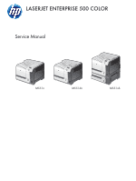 1
1 -
 2
2 -
 3
3 -
 4
4 -
 5
5 -
 6
6 -
 7
7 -
8
-
9
-
10
-
11
-
12
-
13
-
14
-
15
-
16
-
17
-
18
-
19
-
20
-
21
-
22
-
23
-
24
-
25
-
26
-
27
-
28
-
29
-
30
-
31
-
32
-
33
-
34
-
35
-
36
-
37
-
38
-
39
-
40
-
41
-
42
-
43
-
44
-
45
-
46
-
47
-
48
-
49
-
50
-
51
-
52
-
53
-
54
-
55
-
56
-
57
-
58
-
59
-
60
-
61
-
62
-
63
-
64
-
65
-
66
-
67
-
68
-
69
-
70
-
71
-
72
-
73
-
74
-
75
-
76
-
77
-
78
-
79
-
80
-
81
-
82
-
83
-
84
-
85
-
86
-
87
-
88
-
89
-
90
-
91
-
92
-
93
-
94
-
95
-
96
-
97
-
98
-
99
-
100
-
101
-
102
-
103
-
104
-
105
-
106
-
107
-
108
-
109
-
110
-
111
-
112
-
113
-
114
-
115
-
116
-
117
-
118
-
119
-
120
-
121
-
122
-
123
-
124
-
125
-
126
-
127
-
128
-
129
-
130
-
131
-
132
-
133
-
134
-
135
-
136
-
137
-
138
-
139
-
140
-
141
-
142
-
143
-
144
-
145
-
146
-
147
-
148
-
149
-
150
-
151
-
152
-
153
-
154
-
155
-
156
-
157
-
158
-
159
-
160
-
161
-
162
-
163
-
164
-
165
-
166
-
167
-
168
-
169
-
170
-
171
-
172
-
173
-
174
-
175
-
176
-
177
-
178
-
179
-
180
-
181
-
182
-
183
-
184
-
185
-
186
-
187
-
188
-
189
-
190
-
191
-
192
-
193
-
194
-
195
-
196
-
197
-
198
-
199
-
200
-
201
-
202
-
203
-
204
-
205
-
206
-
207
-
208
-
209
-
210
-
211
-
212
-
213
-
214
-
215
-
216
-
217
-
218
-
219
-
220
-
221
-
222
-
223
-
224
-
225
-
226
-
227
-
228
-
229
-
230
-
231
-
232
-
233
-
234
-
235
-
236
-
237
-
238
-
239
-
240
-
241
-
242
-
243
-
244
-
245
-
246
-
247
-
248
-
249
-
250
-
251
-
252
-
253
-
254
-
255
-
256
-
257
-
258
-
259
-
260
-
261
-
262
-
263
-
264
-
265
-
266
-
267
-
268
-
269
-
270
-
271
-
272
-
273
-
274
-
275
-
276
-
277
-
278
-
279
-
280
-
281
-
282
-
283
-
284
-
285
-
286
-
287
-
288
-
289
-
290
-
291
-
292
-
293
-
294
-
295
-
296
-
297
-
298
-
299
-
300
-
301
-
302
-
303
-
304
-
305
-
306
-
307
-
308
-
309
-
310
-
311
-
312
-
313
-
314
-
315
-
316
-
317
-
318
-
319
-
320
-
321
-
322
-
323
-
324
-
325
-
326
-
327
-
328
-
329
-
330
-
331
-
332
-
333
-
334
-
335
-
336
-
337
-
338
-
339
-
340
-
341
-
342
-
343
-
344
-
345
-
346
-
347
-
348
-
349
-
350
-
351
-
352
-
353
-
354
-
355
-
356
-
357
-
358
-
359
-
360
-
361
-
362
-
363
-
364
-
365
-
366
-
367
-
368
-
369
-
370
-
371
-
372
-
373
-
374
-
375
-
376
-
377
-
378
-
379
-
380
-
381
-
382
-
383
-
384
-
385
-
386
-
387
-
388
-
389
-
390
-
391
-
392
-
393
-
394
-
395
-
396
-
397
-
398
-
399
-
400
-
401
-
402
-
403
-
404
-
405
-
406
-
407
-
408
-
409
-
410
-
411
-
412
-
413
-
414
-
415
-
416
-
417
-
418
-
419
-
420
-
421
-
422
-
423
-
424
-
425
-
426
-
427
-
428
-
429
-
430
-
431
-
432
-
433
-
434
-
435
-
436
-
437
-
438
-
439
-
440
-
441
-
442
-
443
-
444
-
445
-
446
-
447
-
448
-
449
-
450
-
451
-
452
-
453
-
454
-
455
-
456
-
457
-
458
-
459
-
460
-
461
-
462
-
463
-
464
-
465
-
466
-
467
-
468
-
469
-
470
-
471
-
472
-
473
-
474
-
475
-
476
-
477
-
478
-
479
-
480
-
481
-
482
-
483
-
484
-
485
-
486
-
487
-
488
-
489
-
490
-
491
-
492
-
493
-
494
-
495
-
496
-
497
-
498
-
499
-
500
-
501
-
502
-
503
-
504
-
505
-
506
-
507
-
508
-
509
-
510
-
511
-
512
-
513
-
514
-
515
-
516
-
517
-
518
-
519
-
520
-
521
-
522
-
523
-
524
-
525
-
526
-
527
-
528
-
529
-
530
-
531
-
532
-
533
-
534
-
535
-
536
-
537
-
538
-
539
-
540
-
541
-
542
-
543
-
544
-
545
-
546
-
547
-
548
-
549
-
550
-
551
-
552
-
553
-
554
-
555
-
556
-
557
-
558
-
559
-
560
-
561
-
562
-
563
-
564
-
565
-
566
-
567
-
568
-
569
-
570
-
571
-
572
-
573
-
574
-
575
-
576
-
577
-
578
-
579
-
580
-
581
-
582
-
583
-
584
-
585
-
586
-
587
-
588
-
589
-
590
-
591
-
592
-
593
-
594
-
595
-
596
-
597
-
598
-
599
-
600
-
601
-
602
-
603
-
604
-
605
-
606
-
607
-
608
-
609
-
610
-
611
-
612
-
613
-
614
-
615
-
616
-
617
-
618
-
619
-
620
-
621
-
622
-
623
-
624
-
625
-
626
-
627
-
628
-
629
-
630
-
631
-
632
-
633
-
634
-
635
-
636
-
637
-
638
-
639
-
640
-
641
-
642
-
643
-
644
-
645
-
646
 |
 |
LASERJET ENTERPRISE 500 COLOR
Service Manual
M551n
M551dn
M551xh