HP StorageWorks 8/80 EZSwitchSetup Administrator's Guide v6.3.0 (53-1001344-01 - Page 21
Set Switch IP Address, Parity: none
 |
View all HP StorageWorks 8/80 manuals
Add to My Manuals
Save this manual to your list of manuals |
Page 21 highlights
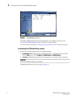
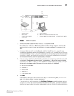
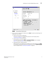
Installing and running the EZSwitchSetup wizard 2 2 3 1 IOIOI ! 0 1 2 3 4 5 6 7 8 9 10 11 12 13 14 15 4 C5 6 7 1 Brocade switch 2 Power cable 3 Ethernet hub or switch 4 Serial cable 5 Setup computer 6 Ethernet cable from hub to Brocade switch 7 Ethernet cable from setup computer to Ethernet hub or switch FIGURE 6 Cable connections 3. Connect the power cord to the switch and plug in to a power source. The switch power and status LEDs display amber and then change to green, which usually takes from one to three minutes. See your switch hardware manual for the location of the LEDs. 4. Connect an Ethernet cable from the Brocade switch to the LAN you want to use for your management connection through an Ethernet hub or switch. If you chose to use your Ethernet connection for Set up in step 1, this is the connection you will use. If you chose the serial cable connection in step 1, you should still connect the Ethernet cable so the Ethernet connection will be available when you start the EZSwitchSetup manager. 5. If you are using a serial connection for set up, connect your setup computer to the serial port on the switch, using the serial cable shipped with the switch. If you cannot locate the serial cable that came with the switch, you will need to find one that has the appropriate connectors. Do not use a null-modem cable. The serial connection settings are as follows. • Bits per second: 9600 • Databits: 8 • Parity: none • Stop bits: 1 • Flow control: none 6. Click Next. EZSwitchSetup attempts to discover the switch. If your switch discovery fails, see Table 2 on page 15 for details on how to recover your switch. If you are using the serial connection, the Set Switch IP Address screen is displayed, and you can go to step 5. You can now remove the serial cable from the switch, but keep it available in case you lose your network connection, and need to revise any of the information you entered. EZSwitchSetup Administrator's Guide 9 53-1001344-01
-
 1
1 -
2
-
3
-
4
-
5
-
6
-
7
-
8
-
9
-
10
-
11
-
12
-
13
-
14
-
15
-
 16
16 -
 17
17 -
 18
18 -
 19
19 -
 20
20 -
 21
21 -
 22
22 -
 23
23 -
 24
24 -
 25
25 -
 26
26 -
27
-
28
-
29
-
30
-
31
-
32
-
33
-
34
-
35
-
36
-
37
-
38
-
39
-
40
-
41
-
42
-
43
-
44
-
45
-
46
-
47
-
48
-
49
-
50
-
51
-
52
-
53
-
54
-
55
-
56
-
57
-
58
-
59
-
60
-
61
-
62
-
63
-
64
 |
 |
