HP StorageWorks 8/80 HP StorageWorks 8-Gb SAN Switch hardware reference manual - Page 43
This also applies to the Encryption SAN Switch and the FCoE Converged Network Switch.
 |
View all HP StorageWorks 8/80 manuals
Add to My Manuals
Save this manual to your list of manuals |
Page 43 highlights
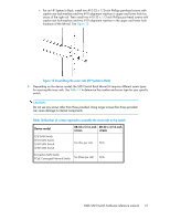
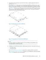
7. Secure the two inner rails (one on each side) to the device, using the appropriate number of screws (see Table 10). For example, Figure 16 shows an inner rail attached to the MP Router with three screws using the two rail screw holes marked R , and one marked 16. Attaching both rails require six screws. This figure also applies to the Encryption SAN Switch and the FCoE Converged Network Switch. Also, Figure 17 shows an inner rail attached to the 4/64 SAN Switch with five screws using the rail screw holes marked 16. Attaching both rails require ten screws. This figure also applies to the 8/8, 8/24, 8/40, and 8/80 SAN Switches. Figure 16 Securing the inner rails to an MP Router Figure 17 Securing the inner rails to the 4/64 SAN Switch NOTE: For factory integration only, tighten the #8-32 x 5/16-inch Phillips pan-head SEMS screws and torque between 6 and 8 inch-pounds. 8. If installing one of the following switches, install the plenum that ships in the switch accessory kit: • 8/8 SAN Switch • 8/24 SAN Switch See "Installing the plenum (if required)" on page 44 for complete installation instructions. See "Securing the switch to the outer rails" on page 44 if not installing one of the devices listed in Step 8, to complete the rack mount procedure. 8-Gb SAN Switch hardware reference manual 43
-
 1
1 -
2
-
3
-
4
-
5
-
6
-
7
-
8
-
9
-
10
-
11
-
12
-
13
-
14
-
15
-
16
-
17
-
18
-
19
-
20
-
21
-
22
-
23
-
24
-
25
-
26
-
27
-
28
-
29
-
30
-
31
-
32
-
33
-
34
-
35
-
36
-
37
-
 38
38 -
 39
39 -
 40
40 -
 41
41 -
 42
42 -
 43
43 -
 44
44 -
 45
45 -
 46
46 -
 47
47 -
 48
48 -
49
-
50
-
51
-
52
-
53
-
54
-
55
-
56
-
57
-
58
-
59
-
60
-
61
-
62
-
63
-
64
-
65
-
66
-
67
-
68
-
69
-
70
-
71
-
72
-
73
-
74
-
75
-
76
-
77
-
78
-
79
-
80
-
81
-
82
-
83
-
84
-
85
-
86
-
87
-
88
-
89
-
90
-
91
-
92
-
93
-
94
-
95
-
96
-
97
-
98
-
99
-
100
-
101
-
102
-
103
-
104
-
105
-
106
-
107
-
108
-
109
-
110
 |
 |
