HP StorageWorks 8/80 HP StorageWorks 8-Gb SAN Switch hardware reference manual - Page 75
Do not force the installation. If the fan assembly does not slide in easily, ensure that
 |
View all HP StorageWorks 8/80 manuals
Add to My Manuals
Save this manual to your list of manuals |
Page 75 highlights
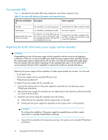
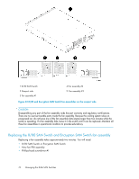
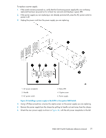
CAUTION: The 8/80 and Encryption SAN Switches use two power cords. Disconnect both power cords before servicing. To replace a fan assembly: 1. Use a Phillips-head screwdriver to unscrew the captive screw on the fan assembly you are replacing. 2. Remove the fan assembly from the chassis by pulling the handle out, away from the chassis. 3. Install the new fan assembly in the chassis: a. Orient the new fan assembly as shown in Figure 33, with the captive screw on the right. b. Gently push the fan assembly into the chassis until it is firmly in. CAUTION: Do not force the installation. If the fan assembly does not slide in easily, ensure that it is correctly oriented before continuing. c. Secure the fan assembly to the chassis with the captive screw. 4. Verify that the fan status LED is lit steady green to indicate normal operation (see Table 16). 5. Optionally, display the fan status using the fanShow command from the CLI (see Figure 33 for the locations of Fan assembly #1, Fan assembly #2, and Fan assembly #3). 8-Gb SAN Switch hardware reference manual 75
-
 1
1 -
2
-
3
-
4
-
5
-
6
-
7
-
8
-
9
-
10
-
11
-
12
-
13
-
14
-
15
-
16
-
17
-
18
-
19
-
20
-
21
-
22
-
23
-
24
-
25
-
26
-
27
-
28
-
29
-
30
-
31
-
32
-
33
-
34
-
35
-
36
-
37
-
38
-
39
-
40
-
41
-
42
-
43
-
44
-
45
-
46
-
47
-
48
-
49
-
50
-
51
-
52
-
53
-
54
-
55
-
56
-
57
-
58
-
59
-
60
-
61
-
62
-
63
-
64
-
65
-
66
-
67
-
68
-
69
-
 70
70 -
 71
71 -
 72
72 -
 73
73 -
 74
74 -
 75
75 -
 76
76 -
 77
77 -
 78
78 -
 79
79 -
 80
80 -
81
-
82
-
83
-
84
-
85
-
86
-
87
-
88
-
89
-
90
-
91
-
92
-
93
-
94
-
95
-
96
-
97
-
98
-
99
-
100
-
101
-
102
-
103
-
104
-
105
-
106
-
107
-
108
-
109
-
110
 |
 |