IBM 436854u User Manual - Page 43
Number, DIMMs, Installation, sequence, connectors
 |
UPC - 883436026772
View all IBM 436854u manuals
Add to My Manuals
Save this manual to your list of manuals |
Page 43 highlights
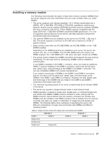
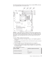
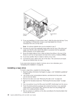
The following illustration shows the dual inline memory module (DIMM) connectors and corresponding LEDs on the system board. DIMM 1 DIMM 2 DIMM 3 DIMM 4 LED LED LED LED DIMM 1 DIMM 2 DIMM 3 DIMM 4 Attention: Static electricity that is released to internal server components when the server is powered-on might cause the server to stop, which might result in the loss of data. To avoid this potential problem, always use an electrostatic-discharge wrist strap or other grounding system when you work inside the server with the power on. To install a DIMM, complete the following steps: 1. Read the safety information that begins on page v and "Installation guidelines" on page 20. 2. Turn off the server and peripheral devices, and disconnect the power cords and all external cables. 3. Remove the side cover (see "Removing the side cover" on page 24). 4. Locate the DIMM connectors on the system board. Determine the connectors into which you will install the DIMMs. Install the DIMMs in the sequence shown in the following table. Table 5. DIMM installation sequence Number of DIMMs 1 Installation sequence (connectors) 1 2 (interleaved configuration) 1, 3 3 4 (interleaved configuration) Not supported 1, 3, 2, 4 Chapter 2. Installing optional devices 29
-
 1
1 -
2
-
3
-
4
-
5
-
6
-
7
-
8
-
9
-
10
-
11
-
12
-
13
-
14
-
15
-
16
-
17
-
18
-
19
-
20
-
21
-
22
-
23
-
24
-
25
-
26
-
27
-
28
-
29
-
30
-
31
-
32
-
33
-
34
-
35
-
36
-
37
-
 38
38 -
 39
39 -
 40
40 -
 41
41 -
 42
42 -
 43
43 -
 44
44 -
 45
45 -
 46
46 -
 47
47 -
 48
48 -
49
-
50
-
51
-
52
-
53
-
54
-
55
-
56
-
57
-
58
-
59
-
60
-
61
-
62
-
63
-
64
-
65
-
66
-
67
-
68
-
69
-
70
-
71
-
72
-
73
-
74
-
75
-
76
-
77
-
78
-
79
-
80
-
81
-
82
-
83
-
84
-
85
-
86
-
87
-
88
-
89
-
90
-
91
-
92
-
93
-
94
-
95
-
96
-
97
-
98
-
99
-
100
-
101
-
102
 |
 |
