IBM 436854u User Manual - Page 49
Tape drive, EMC shield, Drive retainer clip
 |
UPC - 883436026772
View all IBM 436854u manuals
Add to My Manuals
Save this manual to your list of manuals |
Page 49 highlights
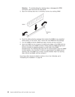
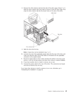
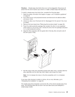
8. Remove the drive retainer clip from the side of the drive cage of bays 1 or 2. Slide the drive retainer clip to the right to remove it from the drive cage; then, snap the drive retainer clip into the screw holes on the side of the drive. EMC shield Tape drive Drive retainer clip 9. Slide the drive into the bay. Note: A tape drive can be installed in bay 1 or 2. 10. Connect one end of the applicable signal cable into the rear of the drive and make sure that the other end of this cable is connected into the applicable connector on the system board. 11. Route the signal cable so that it does not block the airflow to the rear of the drives or over the microprocessor and dual inline memory modules (DIMMs). 12. If you have another drive to install or remove, do so now. 13. Connect the power cable to the rear of the drive. The connectors are keyed and can be inserted only one way. If you have other devices to install or remove, do so now; otherwise, go to "Completing the installation" on page 52. Chapter 2. Installing optional devices 35
-
 1
1 -
2
-
3
-
4
-
5
-
6
-
7
-
8
-
9
-
10
-
11
-
12
-
13
-
14
-
15
-
16
-
17
-
18
-
19
-
20
-
21
-
22
-
23
-
24
-
25
-
26
-
27
-
28
-
29
-
30
-
31
-
32
-
33
-
34
-
35
-
36
-
37
-
38
-
39
-
40
-
41
-
42
-
43
-
 44
44 -
 45
45 -
 46
46 -
 47
47 -
 48
48 -
 49
49 -
 50
50 -
 51
51 -
 52
52 -
 53
53 -
 54
54 -
55
-
56
-
57
-
58
-
59
-
60
-
61
-
62
-
63
-
64
-
65
-
66
-
67
-
68
-
69
-
70
-
71
-
72
-
73
-
74
-
75
-
76
-
77
-
78
-
79
-
80
-
81
-
82
-
83
-
84
-
85
-
86
-
87
-
88
-
89
-
90
-
91
-
92
-
93
-
94
-
95
-
96
-
97
-
98
-
99
-
100
-
101
-
102
 |
 |
