IBM 436854u User Manual - Page 52
hot-swap, drives, Installing, simple-swap, drive
 |
UPC - 883436026772
View all IBM 436854u manuals
Add to My Manuals
Save this manual to your list of manuals |
Page 52 highlights
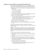
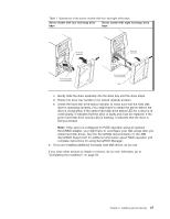
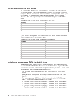
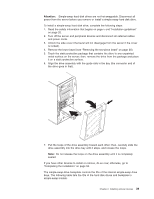
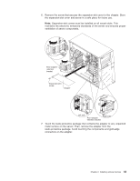
IDs for hot-swap hard disk drives On some models, the hot-swap-drive backplane controls the IDs of the internal hot-swap drive bays. The following table lists the IDs of the hard disk drives and backplane that are connected to one channel in the hot-swap models. In the typical configuration, the standard hard disk drives and backplane are connected to channel A. This table applies only to server models that support four hard disk drives. Table 8. IDs of the hot-swap drives (models with four drive bays) Drive bay ID 4 0 5 1 6 2 7 3 If your server is the eight-bay, 2.5 inch hot-swap SAS model, the IDs of the hard disk drives are shown in the following table. Table 9. IDs of the hot-swap drives (models with eight drive bays) Drive bay ID 4 0 5 1 6 2 7 3 8 4 9 5 10 6 11 7 Installing a simple-swap SATA hard disk drive Some server models support 3.5-inch simple-swap SATA hard disk drives, which are accessible from the front of the server. You must disconnect all power from the server before remove or install simple-swap drives. Before you install a simple-swap SATA hard disk drive, read the following information: v You can install four simple-swap SATA hard disk drives in the simple-swap models. v Install the drives starting from the top bay to the bottom bay (bay 4, 5, 6, and then 7). v The four simple-swap SATA hard disk drive connects to the SATA 0 through SATA 3 connectors on the system board as follows: - The drive in bay 4 connects to the SATA 0 connector on the system board. - The drive in bay 5 connects to the SATA 1 connector on the system board. - The drive in bay 6 connects to the SATA 2 connector on the system board. - The drive in bay 7 connects to the SATA 3 connector on the system board. - 38 System x3200 M2 Types 4367 and 4368: User's Guide
-
 1
1 -
2
-
3
-
4
-
5
-
6
-
7
-
8
-
9
-
10
-
11
-
12
-
13
-
14
-
15
-
16
-
17
-
18
-
19
-
20
-
21
-
22
-
23
-
24
-
25
-
26
-
27
-
28
-
29
-
30
-
31
-
32
-
33
-
34
-
35
-
36
-
37
-
38
-
39
-
40
-
41
-
42
-
43
-
44
-
45
-
46
-
 47
47 -
 48
48 -
 49
49 -
 50
50 -
 51
51 -
 52
52 -
 53
53 -
 54
54 -
 55
55 -
 56
56 -
 57
57 -
58
-
59
-
60
-
61
-
62
-
63
-
64
-
65
-
66
-
67
-
68
-
69
-
70
-
71
-
72
-
73
-
74
-
75
-
76
-
77
-
78
-
79
-
80
-
81
-
82
-
83
-
84
-
85
-
86
-
87
-
88
-
89
-
90
-
91
-
92
-
93
-
94
-
95
-
96
-
97
-
98
-
99
-
100
-
101
-
102
 |
 |
