IBM 436854u User Manual - Page 60
Installing, optional, mini-PCI-X, enablement
 |
UPC - 883436026772
View all IBM 436854u manuals
Add to My Manuals
Save this manual to your list of manuals |
Page 60 highlights
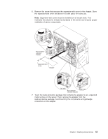
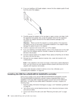
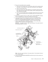
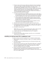
9. Take the other end of the signal cable that is attached to the drive backplane section for drive bays 0 through 3 (as labeled on the front of the drive cage) and connect it to the connector that is closest to the battery on the ServeRAID-MR10i SAS/SATA controller. If drives are installed in drive bays 4 through 7 (as labeled on the front of the drive cage), take the other end of the signal cable that is attached to drive backplane section for drive bays 4 through 7 and connect it to the connector that is farthest from the battery on the ServeRAID-MR10i SAS/SATA controller. 10. Replace the hard disk drive fan assembly: a. Insert the hard disk drive fan assembly retaining tab over the right edge of the hard disk drive backplane; then, rotate the hard disk drive fan assembly toward the backplane. Do not fully close the hard disk drive fan assembly. b. Route the signal cables and power cable through the slot on the edge of the hard disk drive fan assembly. Make sure that the cables will not be pinched between the hard disk drive fan assembly and the hard disk drive backplane when the assembly is installed. c. Rotate the hard disk drive fan assembly toward the backplane until the release tabs are fully engaged and snap into place. 11. Reconnect the hard disk drive fan assembly cable to the system board. 12. Rotate the drive cage back into the server until it stops; then, press and hold the retaining tab on top of the drive cage while you rotate the drive cage into the chassis until it is in the closed position. 13. Reinstall the hard disk drives. Note: Before you continue, check all internal power cables to make sure that they are connected to the system board and other optional devices. 14. Install the side cover (see "Reinstalling the side cover" on page 54). 15. Lock the side cover. 16. Reconnect the external cables and power cords; then, turn on the attached devices and turn on the server. Installing an optional mini-PCI-X enablement card To install an optional mini-PCI-X enablement card, complete the following steps: 1. Read the safety information that begins on page v and "Installation guidelines" on page 20. 2. Turn off the server and all attached devices; then, disconnect all power cords and external cables. 3. Unlock and remove the side cover (see "Removing the side cover" on page 24). 4. Touch the static-protective package that contains the mini-PCI-X enablement card to any unpainted surface on the outside of the server; then, remove mini-PCI-X enablement card from the package. 5. Position the mini-PCI-X enablement card over the mini-PCI slot connector and the plastic standoff. Press the mini-PCI-X enablement card firmly into the mini-PCI slot connector and into the mini-PCI-X enablement card connector, and then onto the plastic standoff. 46 System x3200 M2 Types 4367 and 4368: User's Guide
-
 1
1 -
2
-
3
-
4
-
5
-
6
-
7
-
8
-
9
-
10
-
11
-
12
-
13
-
14
-
15
-
16
-
17
-
18
-
19
-
20
-
21
-
22
-
23
-
24
-
25
-
26
-
27
-
28
-
29
-
30
-
31
-
32
-
33
-
34
-
35
-
36
-
37
-
38
-
39
-
40
-
41
-
42
-
43
-
44
-
45
-
46
-
47
-
48
-
49
-
50
-
51
-
52
-
53
-
54
-
 55
55 -
 56
56 -
 57
57 -
 58
58 -
 59
59 -
 60
60 -
 61
61 -
 62
62 -
 63
63 -
 64
64 -
 65
65 -
66
-
67
-
68
-
69
-
70
-
71
-
72
-
73
-
74
-
75
-
76
-
77
-
78
-
79
-
80
-
81
-
82
-
83
-
84
-
85
-
86
-
87
-
88
-
89
-
90
-
91
-
92
-
93
-
94
-
95
-
96
-
97
-
98
-
99
-
100
-
101
-
102
 |
 |
