IBM 436854u User Manual - Page 58
Installing, ServeRAID-MR10i, SAS/SATA, controller
 |
UPC - 883436026772
View all IBM 436854u manuals
Add to My Manuals
Save this manual to your list of manuals |
Page 58 highlights
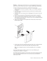
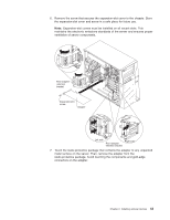
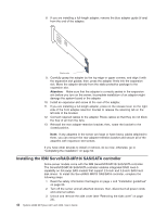
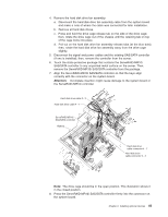
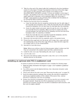
8. If you are installing a full-length adapter, remove the blue adapter guide (if any) from the end of the adapter. Adapter guide 9. Carefully grasp the adapter by the top edge or upper corners, and align it with the expansion slot guides; then, press the adapter firmly into the expansion slot. Move the adapter directly from the static-protective package to the expansion slot. Attention: Make sure that the adapter is correctly seated in the expansion slot before you turn on the server. Incomplete installation of an adapter might damage the system board or the adapter. 10. Install an expansion-slot screw at the rear of the adapter. 11. If you are installing a full-length adapter, press on the release lever on the right side of the front adapter-retention bracket to release the retaining tab on the left side of the bracket. 12. Connect required cables to the adapter. Route cables so that they do not block the flow of air from the fans. 13. Reinstall the rear adapter-retention bracket; then, rotate the bracket to the closed position. Note: If any adapters in the server are large or have heavy cables attached to them, you can remove the rear adapter-retention bracket and secure all of the adapters with expansion-slot screws. If you have other devices to install or remove, do so now; otherwise, go to "Completing the installation" on page 52. Installing the IBM ServeRAID-MR10i SAS/SATA controller Some server models come with the IBM ServeRAID-MR10i SAS/SATA controller. The ServeRAID-MR10i SAS/SATA controller enables integrated RAID level-5 capability on hot-swap SAS models that support 2.5-inch and 3.5-inch SAS hard disk drives. To install the ServeRAID-MR10i SAS/SATA controller, complete the following steps: 1. Read the safety information that begins on page v and "Installation guidelines" on page 20. 2. Turn off the server and all attached devices; then, disconnect all power cords and external cables. 3. Unlock and remove the side cover (see "Removing the side cover" on page 24). 44 System x3200 M2 Types 4367 and 4368: User's Guide
-
 1
1 -
2
-
3
-
4
-
5
-
6
-
7
-
8
-
9
-
10
-
11
-
12
-
13
-
14
-
15
-
16
-
17
-
18
-
19
-
20
-
21
-
22
-
23
-
24
-
25
-
26
-
27
-
28
-
29
-
30
-
31
-
32
-
33
-
34
-
35
-
36
-
37
-
38
-
39
-
40
-
41
-
42
-
43
-
44
-
45
-
46
-
47
-
48
-
49
-
50
-
51
-
52
-
 53
53 -
 54
54 -
 55
55 -
 56
56 -
 57
57 -
 58
58 -
 59
59 -
 60
60 -
 61
61 -
 62
62 -
 63
63 -
64
-
65
-
66
-
67
-
68
-
69
-
70
-
71
-
72
-
73
-
74
-
75
-
76
-
77
-
78
-
79
-
80
-
81
-
82
-
83
-
84
-
85
-
86
-
87
-
88
-
89
-
90
-
91
-
92
-
93
-
94
-
95
-
96
-
97
-
98
-
99
-
100
-
101
-
102
 |
 |
