IBM 436854u User Manual - Page 50
Installing, hot-swap, drive
 |
UPC - 883436026772
View all IBM 436854u manuals
Add to My Manuals
Save this manual to your list of manuals |
Page 50 highlights
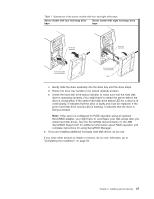
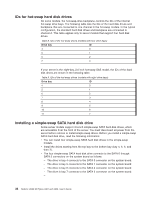
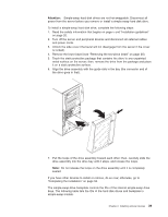
Installing a hot-swap SAS or hot-swap SATA hard disk drive Some hot-swap SAS models support 2.5-inch or 3.5-inch hot-swap SAS hard disk drives. The hot-swap SATA models support 3.5-inch hot-swap SATA hard disk drives. Before you install a hot-swap hard disk drive, read the following information: v Depending on your model, the server supports the following maximum number of hot-swap drives: - Four 3.5-inch hot-swap SAS - Four 3.5-inch hot-swap SATA - Four 2.5-inch hot-swap SAS - Eight 2.5-inch hot-swap SAS v You must install either all SAS hard disk drives or all SATA hard disk drives in the server. Do not install both SAS and SATA drives in the server. v Install drives in the following sequence: - For server models that support four hard disk drives, install the drives starting from the top bay to the bottom bay (bay 4, 5, 6, and then 7). - For server models that support eight hard disk drives, install the drives starting from left to right (bay 4, 5, 6, 7, 8, 9, 10, and then 11). v Inspect the drive tray for signs of damage. v Make sure that the drive is correctly installed in the tray. v You do not have to turn off the server to install hot-swap drives in the hot-swap drive bays. The server hot-swap bays are connected to a SAS/SATA backplane. This backplane, also known as the hot-swap-drive backplane, is the printed circuit board behind these bays. Attention: Static electricity that is released to internal server components when the server is powered-on might cause the server to stop, which might result in the loss of data. To avoid this potential problem, always use an electrostatic-discharge wrist strap or other grounding system when you work inside the server with the power on. To install a hot-swap hard disk drive, complete the following steps: 1. Read the safety information that begins on page v and "Installation guidelines" on page 20. 2. Unlock the side cover (the bezel will not disengage from the server if the cover is locked). 3. Remove the lower bezel (see "Removing the two-piece bezel" on page 25). 4. Touch the static-protective package that contains the drive to any unpainted metal surface on the server; then, remove the drive from the package and place it on a static-protective surface. 5. Install the hard disk drive in the hot-swap bay: a. Make sure that the drive tray handle is open. b. Align the drive assembly with the guide rails in the bay as shown in the following illustrations based on your model. 36 System x3200 M2 Types 4367 and 4368: User's Guide
-
 1
1 -
2
-
3
-
4
-
5
-
6
-
7
-
8
-
9
-
10
-
11
-
12
-
13
-
14
-
15
-
16
-
17
-
18
-
19
-
20
-
21
-
22
-
23
-
24
-
25
-
26
-
27
-
28
-
29
-
30
-
31
-
32
-
33
-
34
-
35
-
36
-
37
-
38
-
39
-
40
-
41
-
42
-
43
-
44
-
 45
45 -
 46
46 -
 47
47 -
 48
48 -
 49
49 -
 50
50 -
 51
51 -
 52
52 -
 53
53 -
 54
54 -
 55
55 -
56
-
57
-
58
-
59
-
60
-
61
-
62
-
63
-
64
-
65
-
66
-
67
-
68
-
69
-
70
-
71
-
72
-
73
-
74
-
75
-
76
-
77
-
78
-
79
-
80
-
81
-
82
-
83
-
84
-
85
-
86
-
87
-
88
-
89
-
90
-
91
-
92
-
93
-
94
-
95
-
96
-
97
-
98
-
99
-
100
-
101
-
102
 |
 |
