IBM 436854u User Manual - Page 59
controller.
 |
UPC - 883436026772
View all IBM 436854u manuals
Add to My Manuals
Save this manual to your list of manuals |
Page 59 highlights
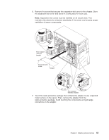
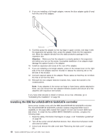
4. Remove the hard disk drive fan assembly: a. Disconnect the hard disk drive fan assembly cable from the system board and make a note of where the cable was connected for later installation. b. Remove all hard disk drives. c. Press and hold the drive cage release tab on the side of the drive cage; then, rotate the drive cage out of the chassis until the retaining tab on top of the cage locks into place. d. Pull out on the hard disk drive fan assembly release tabs (at the blue dots); then, rotate the hard disk drive fan assembly away from the drive cage slightly. 5. Disconnect the signal and power cables and the existing SAS/SATA controller (if one is installed); then, remove the controller from the server. 6. Touch the static-protective package that contains the ServeRAID-MR10i SAS/SATA controller to any unpainted metal surface on the server. Then, remove the ServeRAID-MR10i SAS/SATA controller from the package. 7. Align the ServeRAID-MR10i SAS/SATA controller so that the keys align correctly with the connector on the system board. Attention: Incomplete insertion might cause damage to the system board or the ServeRAID-MR10i controller. Hard disk drive cable 0 - 3 Hard disk drive cable 4 - 7 ServeRAID-MR10i SAS/SATA controller Battery Hard disk drive cable connector 4 - 7 Hard disk drive cable connector 0 - 3 Note: The drive cage should be in the open position. This illustration shows it in the closed position. 8. Press the ServeRAID-MR10i SAS/SATA controller firmly into the connector on the system board. Chapter 2. Installing optional devices 45
-
 1
1 -
2
-
3
-
4
-
5
-
6
-
7
-
8
-
9
-
10
-
11
-
12
-
13
-
14
-
15
-
16
-
17
-
18
-
19
-
20
-
21
-
22
-
23
-
24
-
25
-
26
-
27
-
28
-
29
-
30
-
31
-
32
-
33
-
34
-
35
-
36
-
37
-
38
-
39
-
40
-
41
-
42
-
43
-
44
-
45
-
46
-
47
-
48
-
49
-
50
-
51
-
52
-
53
-
 54
54 -
 55
55 -
 56
56 -
 57
57 -
 58
58 -
 59
59 -
 60
60 -
 61
61 -
 62
62 -
 63
63 -
 64
64 -
65
-
66
-
67
-
68
-
69
-
70
-
71
-
72
-
73
-
74
-
75
-
76
-
77
-
78
-
79
-
80
-
81
-
82
-
83
-
84
-
85
-
86
-
87
-
88
-
89
-
90
-
91
-
92
-
93
-
94
-
95
-
96
-
97
-
98
-
99
-
100
-
101
-
102
 |
 |
