IBM 79856au User Guide - Page 33
System-board, internal, cable, connectors, Power-backplane-card
 |
UPC - 883436004374
View all IBM 79856au manuals
Add to My Manuals
Save this manual to your list of manuals |
Page 33 highlights
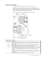
System-board internal cable connectors The following illustration shows the internal connectors on the system board. SATA tape drive signal External SAS Internal SAS Power backplane Operator panel CD/DVD signal Internal USB Tape drive power Front USB Front video CD/DVD power Power-backplane-card internal cable connectors The following illustration shows the internal connectors on the power-backplane card. System-board connector Fan 10 connector Hard disk drive power connector Fan 7 connector Chapter 2. Installing optional devices 19
-
 1
1 -
2
-
3
-
4
-
5
-
6
-
7
-
8
-
9
-
10
-
11
-
12
-
13
-
14
-
15
-
16
-
17
-
18
-
19
-
20
-
21
-
22
-
23
-
24
-
25
-
26
-
27
-
 28
28 -
 29
29 -
 30
30 -
 31
31 -
 32
32 -
 33
33 -
 34
34 -
 35
35 -
 36
36 -
 37
37 -
 38
38 -
39
-
40
-
41
-
42
-
43
-
44
-
45
-
46
-
47
-
48
-
49
-
50
-
51
-
52
-
53
-
54
-
55
-
56
-
57
-
58
-
59
-
60
-
61
-
62
-
63
-
64
-
65
-
66
-
67
-
68
-
69
-
70
-
71
-
72
-
73
-
74
-
75
-
76
-
77
-
78
-
79
-
80
-
81
-
82
-
83
-
84
-
85
-
86
-
87
-
88
-
89
-
90
-
91
-
92
-
93
-
94
-
95
-
96
-
97
-
98
-
99
-
100
-
101
-
102
-
103
-
104
-
105
-
106
-
107
-
108
-
109
-
110
-
111
-
112
-
113
-
114
-
115
-
116
-
117
-
118
 |
 |

System-board
internal
cable
connectors
The
following
illustration
shows
the
internal
connectors
on
the
system
board.
External SAS
Internal SAS
Power backplane
Internal USB
Tape drive power
Front USB
Front video
CD/DVD power
CD/DVD signal
Operator panel
SATA tape drive
signal
Power-backplane-card
internal
cable
connectors
The
following
illustration
shows
the
internal
connectors
on
the
power-backplane
card.
System-board
connector
Hard disk drive
power connector
Fan 10 connector
Fan 7 connector
Chapter
2.
Installing
optional
devices
19