IBM 79856au User Guide - Page 41
Installation
 |
UPC - 883436004374
View all IBM 79856au manuals
Add to My Manuals
Save this manual to your list of manuals |
Page 41 highlights
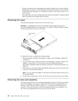
Access holes Release tabs To remove the riser-card assembly, complete the following steps: 1. Read the safety information that begins on page v and "Installation guidelines" on page 23. 2. Make sure that the server and all peripheral devices are turned off, and that the power cords and all external cables are disconnected (see "Turning off the server" on page 13); then, remove the cover (see "Removing the cover" on page 26). 3. Push the two retention latches on the riser-card assembly toward the second microprocessor socket; then, grasp the assembly at the rear and side edges and lift it to remove it from the server. Place the riser-card assembly on a flat, static-protective surface. Chapter 2. Installing optional devices 27
-
 1
1 -
2
-
3
-
4
-
5
-
6
-
7
-
8
-
9
-
10
-
11
-
12
-
13
-
14
-
15
-
16
-
17
-
18
-
19
-
20
-
21
-
22
-
23
-
24
-
25
-
26
-
27
-
28
-
29
-
30
-
31
-
32
-
33
-
34
-
35
-
 36
36 -
 37
37 -
 38
38 -
 39
39 -
 40
40 -
 41
41 -
 42
42 -
 43
43 -
 44
44 -
 45
45 -
 46
46 -
47
-
48
-
49
-
50
-
51
-
52
-
53
-
54
-
55
-
56
-
57
-
58
-
59
-
60
-
61
-
62
-
63
-
64
-
65
-
66
-
67
-
68
-
69
-
70
-
71
-
72
-
73
-
74
-
75
-
76
-
77
-
78
-
79
-
80
-
81
-
82
-
83
-
84
-
85
-
86
-
87
-
88
-
89
-
90
-
91
-
92
-
93
-
94
-
95
-
96
-
97
-
98
-
99
-
100
-
101
-
102
-
103
-
104
-
105
-
106
-
107
-
108
-
109
-
110
-
111
-
112
-
113
-
114
-
115
-
116
-
117
-
118
 |
 |

Access holes
Release tabs
To
remove
the
riser-card
assembly,
complete
the
following
steps:
1.
Read
the
safety
information
that
begins
on
page
v
and
“Installation
guidelines”
on
page
23.
2.
Make
sure
that
the
server
and
all
peripheral
devices
are
turned
off,
and
that
the
power
cords
and
all
external
cables
are
disconnected
(see
“Turning
off
the
server”
on
page
13);
then,
remove
the
cover
(see
“Removing
the
cover”
on
page
26).
3.
Push
the
two
retention
latches
on
the
riser-card
assembly
toward
the
second
microprocessor
socket;
then,
grasp
the
assembly
at
the
rear
and
side
edges
and
lift
it
to
remove
it
from
the
server.
Place
the
riser-card
assembly
on
a
flat,
static-protective
surface.
Chapter
2.
Installing
optional
devices
27