IBM 79856au User Guide - Page 68
Installing, memory, module
 |
UPC - 883436004374
View all IBM 79856au manuals
Add to My Manuals
Save this manual to your list of manuals |
Page 68 highlights
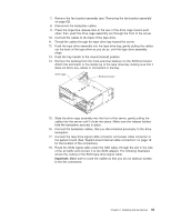
Attention: Do not touch the thermal grease on the bottom of the heat sink or set down the heat sink after you remove the plastic cover. Touching the thermal grease will contaminate it. For details, see the information about thermal grease on page 51. Thermal grease Heat sink a. Make sure that the heat-sink release lever is in the open position. b. Remove the plastic protective cover from the bottom of the heat sink. c. Align the heat sink above the microprocessor with the thermal-grease side down. Press firmly on the heat sink. Retainer bracket Heat sink release lever Microprocessor d. Slide the rear flange of the heat sink into the opening in the retainer bracket. e. Press down firmly on the heat sink until it is seated securely. f. Rotate the heat-sink release lever to the closed position and hook it underneath the lock tab. If you have other devices to install or remove, do so now. Otherwise, go to "Completing the installation" on page 61. Installing a memory module The following notes describe the types of dual inline memory modules (DIMMs) that the server supports and other information that you must consider when installing DIMMs: v The server supports up to 16 Registered DDR2 PC2-5300, 512 MB, 1 GB, 2GB, and 4 GB DIMMs, for a maximum of 64 GB of system memory. See http://www.ibm.com/servers/eserver/serverproven/compat/us/ for a list of memory modules you can use with the server. 54 System x3655 Type 7985: User's Guide
-
 1
1 -
2
-
3
-
4
-
5
-
6
-
7
-
8
-
9
-
10
-
11
-
12
-
13
-
14
-
15
-
16
-
17
-
18
-
19
-
20
-
21
-
22
-
23
-
24
-
25
-
26
-
27
-
28
-
29
-
30
-
31
-
32
-
33
-
34
-
35
-
36
-
37
-
38
-
39
-
40
-
41
-
42
-
43
-
44
-
45
-
46
-
47
-
48
-
49
-
50
-
51
-
52
-
53
-
54
-
55
-
56
-
57
-
58
-
59
-
60
-
61
-
62
-
 63
63 -
 64
64 -
 65
65 -
 66
66 -
 67
67 -
 68
68 -
 69
69 -
 70
70 -
 71
71 -
 72
72 -
 73
73 -
74
-
75
-
76
-
77
-
78
-
79
-
80
-
81
-
82
-
83
-
84
-
85
-
86
-
87
-
88
-
89
-
90
-
91
-
92
-
93
-
94
-
95
-
96
-
97
-
98
-
99
-
100
-
101
-
102
-
103
-
104
-
105
-
106
-
107
-
108
-
109
-
110
-
111
-
112
-
113
-
114
-
115
-
116
-
117
-
118
 |
 |
