IBM 79856au User Guide - Page 55
Installing, optional, drive, 5-inch, model, server
 |
UPC - 883436004374
View all IBM 79856au manuals
Add to My Manuals
Save this manual to your list of manuals |
Page 55 highlights
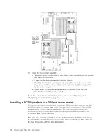
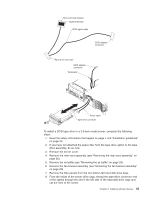
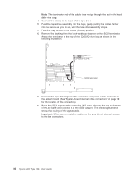
Installing an optional tape drive Prepare the drive according to the instructions that come with the drive, setting any switches or jumpers; then, see "Installing a SATA tape drive in a 3.5-inch model server" or "Installing a SATA tape drive in a 2.5-inch model server" on page 43. Installing a SATA tape drive in a 3.5-inch model server The SATA tape drive must be installed into the two bottom-left hard disk drive bays. If you have hard disk drives in those bays, move the drives to other bays. The cables for the tape drive come with the tape drive option. To install a SATA tape drive in a 3.5-inch model server, complete the following steps: 1. Read the safety information that begins on page v and "Installation guidelines" on page 23. 2. If you have not attached the space filler from the tape drive option to the tape drive assembly, do so now. 3. Remove the server cover. 4. Remove the riser-card assembly (see "Removing the riser-card assembly" on page 26). 5. Remove the air baffle (see "Removing the air baffle" on page 29). 6. Remove the fan-bracket assembly (see "Removing the fan-bracket assembly" on page 60). 7. Remove the filler panels from the two bottom-left hard disk drive bays. 8. From the inside of the server drive cage, thread the tape-drive connector end of the cables through the slot in the left side of the hard disk drive cage and out the front of the server. 9. Connect the cables to the back of the tape drive and route the cable through the cable clamp . 10. Push the tape drive assembly into the bays, gently pulling the cables farther into the server as you do so, until the tape drive assembly stops. 11. Push the tray handle to the closed (locked) position. Chapter 2. Installing optional devices 41
-
 1
1 -
2
-
3
-
4
-
5
-
6
-
7
-
8
-
9
-
10
-
11
-
12
-
13
-
14
-
15
-
16
-
17
-
18
-
19
-
20
-
21
-
22
-
23
-
24
-
25
-
26
-
27
-
28
-
29
-
30
-
31
-
32
-
33
-
34
-
35
-
36
-
37
-
38
-
39
-
40
-
41
-
42
-
43
-
44
-
45
-
46
-
47
-
48
-
49
-
 50
50 -
 51
51 -
 52
52 -
 53
53 -
 54
54 -
 55
55 -
 56
56 -
 57
57 -
 58
58 -
 59
59 -
 60
60 -
61
-
62
-
63
-
64
-
65
-
66
-
67
-
68
-
69
-
70
-
71
-
72
-
73
-
74
-
75
-
76
-
77
-
78
-
79
-
80
-
81
-
82
-
83
-
84
-
85
-
86
-
87
-
88
-
89
-
90
-
91
-
92
-
93
-
94
-
95
-
96
-
97
-
98
-
99
-
100
-
101
-
102
-
103
-
104
-
105
-
106
-
107
-
108
-
109
-
110
-
111
-
112
-
113
-
114
-
115
-
116
-
117
-
118
 |
 |
