IBM 79856au User Guide - Page 66
Microprocessor, Heat sink
 |
UPC - 883436004374
View all IBM 79856au manuals
Add to My Manuals
Save this manual to your list of manuals |
Page 66 highlights
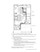
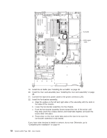
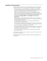
Note: For clarity, certain components have been removed from this illustration. Heat sink Microprocessor Microprocessor socket dust cover Attention: v A startup (boot) microprocessor must always be installed in microprocessor connector 1 on the system board. v To ensure proper server operation when you install an additional microprocessor, use microprocessors that have the same cache size and type, and the same clock speed. Microprocessor internal and external clock frequencies must be identical. Complete the following steps to install an additional microprocessor: 1. Read the safety information that begins on page v and "Installation guidelines" on page 23. 2. Turn off the server and disconnect all power cords and external cables (see "Turning off the server" on page 13); then, remove the server cover (see "Removing the cover" on page 26). 3. Remove the riser card (see "Removing the riser-card assembly" on page 26). 4. Remove the air baffle (see "Removing the air baffle" on page 29). 5. Locate the second microprocessor connector on the system board. 6. Install the microprocessor by completing the following steps: a. Touch the static-protective package containing the microprocessor to any unpainted metal surface on the server. Then, remove the microprocessor from the package. 52 System x3655 Type 7985: User's Guide
-
 1
1 -
2
-
3
-
4
-
5
-
6
-
7
-
8
-
9
-
10
-
11
-
12
-
13
-
14
-
15
-
16
-
17
-
18
-
19
-
20
-
21
-
22
-
23
-
24
-
25
-
26
-
27
-
28
-
29
-
30
-
31
-
32
-
33
-
34
-
35
-
36
-
37
-
38
-
39
-
40
-
41
-
42
-
43
-
44
-
45
-
46
-
47
-
48
-
49
-
50
-
51
-
52
-
53
-
54
-
55
-
56
-
57
-
58
-
59
-
60
-
 61
61 -
 62
62 -
 63
63 -
 64
64 -
 65
65 -
 66
66 -
 67
67 -
 68
68 -
 69
69 -
 70
70 -
 71
71 -
72
-
73
-
74
-
75
-
76
-
77
-
78
-
79
-
80
-
81
-
82
-
83
-
84
-
85
-
86
-
87
-
88
-
89
-
90
-
91
-
92
-
93
-
94
-
95
-
96
-
97
-
98
-
99
-
100
-
101
-
102
-
103
-
104
-
105
-
106
-
107
-
108
-
109
-
110
-
111
-
112
-
113
-
114
-
115
-
116
-
117
-
118
 |
 |
