JVC DLA-HX1U Instruction Manual - Page 7
Controls and Features, Front Side/ Top Surface/ Left Side - manual
 |
View all JVC DLA-HX1U manuals
Add to My Manuals
Save this manual to your list of manuals |
Page 7 highlights
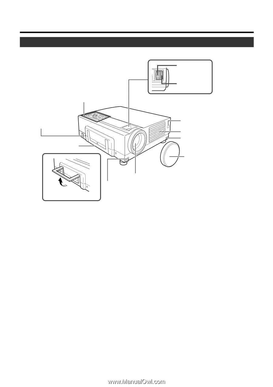
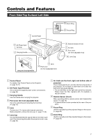
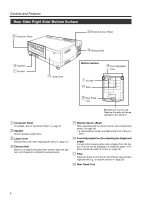
Controls and Features Front Side/ Top Surface/ Left Side 1 Control Panel 2 AC Power Input Terminal 3 Carrying Handle Using the Carrying Handle 5 Lens 4 Foot Lever (for front adjustable foot) p Zoom Ring 9 Focus Ring 8 Remote Sensor (Front) 7 Air Inlet 4 Foot Lever (for front adjustable foot) 6 Lens Cap 1 Control Panel For details, See 'Control Panel on the Projector'. (☞ page 10, 11) 2 AC Power Input Terminal This is where the supplied power cord is connected to. (☞ page 24) 3 Carrying Handle Use this handle when carrying the projector. 4 Foot Lever (for front adjustable foot) Use when extending and retracting the front foot. (☞ page 15) 5 Lens The lens is a 1.3 x (zoom ratio) manual zoom lens. Before projection, remove the lens cap. (☞ page 17, 24) 6 Lens Cap It is recommended that the cap be fitted on the lens to prevent it from becoming dirty when the projector is not in use. (☞ page 24) 7 Air Inlets (on the front, right, and bottom side of projector) The air inlets absorb air to cool the internal components of the projector. Do not block or allow warm air to blow into them as it may cause damage. • The air inlet filter on the right side cannot be removed. Please clean the filter regularly with, for example, a vacuum cleaner. 8 Remote Sensor (Front) When operating with the remote control, aim it towards this sensor. (☞ page 18) • A remote sensor is also provided at the rear of the pro- jector. 9 Focus Ring Used to manually focus the projected image on the screen. (☞ page 26) p Zoom Ring Used to manually zoom the projected image on the screen. (☞ page 26) 7
-
 1
1 -
 2
2 -
 3
3 -
 4
4 -
 5
5 -
 6
6 -
 7
7 -
 8
8 -
 9
9 -
 10
10 -
 11
11 -
 12
12 -
13
-
14
-
15
-
16
-
17
-
18
-
19
-
20
-
21
-
22
-
23
-
24
-
25
-
26
-
27
-
28
-
29
-
30
-
31
-
32
-
33
-
34
-
35
-
36
-
37
-
38
-
39
-
40
-
41
-
42
-
43
-
44
-
45
-
46
-
47
-
48
-
49
-
50
-
51
-
52
-
53
-
54
-
55
-
56
-
57
-
58
-
59
-
60
-
61
-
62
 |
 |