Kyocera KM-5530 DF-600/610 Installation Instructions Rev-2C
Kyocera KM-5530 Manual
 |
View all Kyocera KM-5530 manuals
Add to My Manuals
Save this manual to your list of manuals |
Kyocera KM-5530 manual content summary:
- Kyocera KM-5530 | DF-600/610 Installation Instructions Rev-2C - Page 1
Installation Guide Guide d'installation Guia de instalacion Installationsanleitung Guida all'installazione DF-600/610 Document Finisher Retoucheur de Document Finalizador de Documentos Dokument Finisher Finitrice di Documenti - Kyocera KM-5530 | DF-600/610 Installation Instructions Rev-2C - Page 2
copiers and printers. This can be installed in a similar way for both but different portions of the procedure are written separately. The description given below is intended for service de forma similar para ambas pero las partes que requieren diferentes procedimientos se describen por separado - Kyocera KM-5530 | DF-600/610 Installation Instructions Rev-2C - Page 3
, set the paper type and the attribute of paper type (paper weight) for each drawer referring to the operation guide of the printer/copier. * When using paper for color copying only, select "High quality" and "Custom 1 (to 8)" for the paper type. Remarques concernant l'installation du retoucheur - Kyocera KM-5530 | DF-600/610 Installation Instructions Rev-2C - Page 4
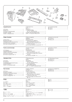
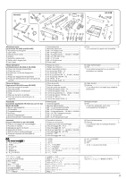
F J K G M L N Supplied parts A Finisher 1 B Main tray 1 C Finisher connecting plate 1 D Stapler cartridge 2 E M4 × 12 binding screw 2 F Hexagonal nut 2 G Pin 2 H Sub tray 1 I Stapler cartridge (for 100 V specifications 1 J Paper insertion aid guide plate 1 K M4 × 10 tap-tight binding - Kyocera KM-5530 | DF-600/610 Installation Instructions Rev-2C - Page 5
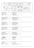
AK-640A o a w i R P Q b x g e d r c h j k l m n pq f u AK-640B t s v Attachment parts [for both the AK-640A and AK-640B] b Assembly mounting plate 1 c Latch plate 1 d Release hook handle 1 e Stopper 2 f Assembly release plate 1 g Safety switch trigger plate 1 h Latch - Kyocera KM-5530 | DF-600/610 Installation Instructions Rev-2C - Page 6
AK-640A o a w i R P Q b x g e d r c h j k l m n pq f u [for the AK-640A only] a Rail unit 1 o M4 × 10 binding screw 4 P Gasket (10 × 5 × 200 1 Q Gasket (10 × 10 × 200 2 R Core 1 [for the AK-640B only] r Left base cover 1 s Front base cover 1 t Finisher junction wire 1 u Assembly - Kyocera KM-5530 | DF-600/610 Installation Instructions Rev-2C - Page 7
0 mm 5 mm Procedure Before installing the finisher, turn the main switch of the copier or printer off and unplug its power cable from the wall outlet. 2 1 2 1 A f P 0 mm 3 mm 1. Remove the screws 1 and then remove the rubber feet 2 from the finisher A. 2. Attach the gasket (10 × 5 × 200) P to - Kyocera KM-5530 | DF-600/610 Installation Instructions Rev-2C - Page 8
screws p to attach the two rubber feet 2 that were removed in step 1 to the assembly release plate f. k f k 4. Make sure that the end of the assembly release plate f that has the positioning pin 3 is located towards the rear side of the copier or printer, and use the two M4 × 14 S-tight screws - Kyocera KM-5530 | DF-600/610 Installation Instructions Rev-2C - Page 9
0 mm 5 mm 45 ± 5 mm b b a b a L Q n 5. Attach a gasket (10 × 10 × 200) Q to the assembly mounting plate b at the location shown in the illustration. Use the two M4 × 20 TPS-tight screws n to attach the assembly mounting plate b at its lowermost position. 6. Attach the connecting sponge L to the - Kyocera KM-5530 | DF-600/610 Installation Instructions Rev-2C - Page 10
the gray handle 0 of the release hook 5. Fit the green release hook handle d with the removed screw 9. 10. Fit the latch plate c with the two pins 6 that were removed in step 8. 7. Retirer la vis 4 puis retirer le crochet de dégagement 5. 8. Retirer les trois aiguilles 67 puis retirer le rail - Kyocera KM-5530 | DF-600/610 Installation Instructions Rev-2C - Page 11
release hook 5 with the screw 4 that was removed in step 7. ! @ ! @ i verrou dans les deux trous ! de la plaque de support et faire glisser latéralement la plaque de verrou h estremità del perno ^ della piastra di connessione i nella parte ritagliata & dell'altro pannello di chiusura c. 13.= - Kyocera KM-5530 | DF-600/610 Installation Instructions Rev-2C - Page 12
i in place. 16. Pull out on the release hook handle d and confirm that the latch plate h operates smoothly. 17. Open the front cover. 18. Remove the four blue screws * locking each of the two separate retainers ) to the intermediate tray ( and detach both retainers ). 19. Pull out the intermediate - Kyocera KM-5530 | DF-600/610 Installation Instructions Rev-2C - Page 13
remove the four strips of fixing tape ‹. 22. Insert a stapler cartridge D into each of the staplers › and fi of the intermediate tray (. Press on the cartridges until they are securely locked. For 100 V specifications only 23. Insert a stapler cartridge fl ubicada en la parte posterior de la bandeja - Kyocera KM-5530 | DF-600/610 Installation Instructions Rev-2C - Page 14
of the sub tray H. 30. Remove the 2-pin connector · from the main tray unit and then remove the five screws , to remove the rear cover Œ. 24. Pousser le la etiqueta A M en la parte escalonada en el lado de la bandeja principal B. 29. Coloque la etiqueta B N en la parte escalonada en el lado de la - Kyocera KM-5530 | DF-600/610 Installation Instructions Rev-2C - Page 15
rail unit a into the lower part of the finisher A. 34. Pull out the intermediate tray (. 35. Fix the rail unit a with the four M4 × 10 binding screws o. 36. Insert the intermediate tray ( into its original position. 31. Retirer les quatre vis „ puis retirer le support inférieur droit ´. 32. Les - Kyocera KM-5530 | DF-600/610 Installation Instructions Rev-2C - Page 16
al punto 44. 39.= Q =‰ !=ˇ 40.= O jQ S !=m !=A !=u 41.= !"#$%&'()*+,QO QP !QQ 42. Reattach the guide plate ˇ in its original position. (Use two of the screws ‰ that were removed in step 39 to fix the upper part of the guide plate ˇ in two places.) 43. Use the other two screws ‰ that were - Kyocera KM-5530 | DF-600/610 Installation Instructions Rev-2C - Page 17
M4 × 6 TP in cromo v per fissare il pannello di base anteriore s in posizione. 45.= ¨= 46.= O s !=s= =Á= !"#=u= !"#$%&' jQ Sqm !=v= !" 47. Remettre le support inférieur droit à sa position d'origine. 48. Remettre le couvercle arrière à sa position d'origine et connecter le connecteur à deux - Kyocera KM-5530 | DF-600/610 Installation Instructions Rev-2C - Page 18
5 mm Q 51. Attach a gasket (10 × 10 × 200) Q to the assembly option box j at the location shown in the illustration. Í Í ∏ Å Î Î l j 52. Remove the screw " and then remove the rear connector cover Å. Insert the two hooks Î on the assembly option box j into the two holes Í and use the remaining - Kyocera KM-5530 | DF-600/610 Installation Instructions Rev-2C - Page 19
screws Ï and then remove the rear cover Ó to the paper feeder ˝. 55. Insert the female connector end Ô of the finisher junction wire t into the hole Æ to secure the connector in place. 56. Insert the male connector end Ò of the finisher junction wire into the connector Ú on the printer. 57. Use - Kyocera KM-5530 | DF-600/610 Installation Instructions Rev-2C - Page 20
boîte d'assemblée d'option j. Brancher le câble d'alimentation sur une prise murale. 59. Utilice alicates u otra herramienta similar para cortar la parte inferior - de la cubierta de conector trasero Å. 60. Utilice el tornillo " para volver a instalar la cubierta de conector trasero Å en su posici - Kyocera KM-5530 | DF-600/610 Installation Instructions Rev-2C - Page 21
again. 66. Close the front cover. 67. Plug the power cable to the copier or printer  back into the wall outlet and turn the main switch back on. 64. g, spostare la piastra di comando g fino a quando la sua parte sporgente non sia allineata con l'interruttore di sicurezza e quindi assicurare di - Kyocera KM-5530 | DF-600/610 Installation Instructions Rev-2C - Page 22
x 2mm 2mm 0.5mm 0.5mm x ¢ 0.5mm 0.5mm Notes in Installing the Punch Unit The film is required only if you install the punch unit to the document finisher. The procedure for installing the film is shown below. 1. Take off the release paper from the film x. 2. Paste the film x to the conveying - Kyocera KM-5530 | DF-600/610 Installation Instructions Rev-2C - Page 23
a b 1 ¿ 2 3 5 4 Correcting Paper Curling 1. Set the machine in the non-sort mode and run paper through the machine to make a test copy. 2. Check if the paper that is ejected from the finisher A is curled. If it is, make the following adjustment. If the Paper Curls Downward (figure "a") 1. - Kyocera KM-5530 | DF-600/610 Installation Instructions Rev-2C - Page 24
¡ ™ 4 5 3 21 £ If the Paper Curls Upward (figure "b") 1. Open the front cover. 2. Remove the three screws ¡ locking down the inner left cover ™ followed by the cover. 3. Rotate the upper lever £ by one mark in the direction of the - Kyocera KM-5530 | DF-600/610 Installation Instructions Rev-2C - Page 25
delle dimensioni seguenti. A4R, A3, B4, LDR (11" × 17") e LTR (11" × 8,5") 2. Distendere i fogli copiati e cuciti centralmente dall'unità, con la parte interna rivolta verso il basso, come mostrato nell'illustrazione. Controllare che i fogli siano cuciti al centro. 3. Se la posizione di cucitura - Kyocera KM-5530 | DF-600/610 Installation Instructions Rev-2C - Page 26
c d 5. Set the setting value for each paper size. If the paper is stapled too far toward the paper eject side (as shown in "c" in the illustration), decrease the setting value. If the paper is stapled too far toward the paper feed side (as shown in "d" in the illustration), increase the setting - Kyocera KM-5530 | DF-600/610 Installation Instructions Rev-2C - Page 27
MEMO: - Kyocera KM-5530 | DF-600/610 Installation Instructions Rev-2C - Page 28
2004. 1 3B881022C
-
 1
1 -
 2
2 -
 3
3 -
 4
4 -
 5
5 -
 6
6 -
 7
7 -
8
-
9
-
10
-
11
-
12
-
13
-
14
-
15
-
16
-
17
-
18
-
19
-
20
-
21
-
22
-
23
-
24
-
25
-
26
-
27
-
28
 |
 |
DF-600/610
Document Finisher
Retoucheur de Document
Finalizador de Documentos
Dokument Finisher
Finitrice di Documenti
±
±²
ドキュメントフィニッシャ
Installation Guide
Guide d'installation
Guia de instalacion
Installationsanleitung
Guida all'installazione
設置手順書