Lenovo A600 Lenovo IdeaCentre A600 Hardware Maintenance Manual - Page 77
Replacing the LCD panel
 |
UPC - 884942547713
View all Lenovo A600 manuals
Add to My Manuals
Save this manual to your list of manuals |
Page 77 highlights
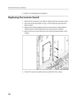
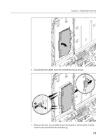
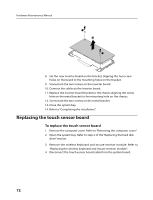
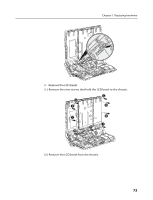
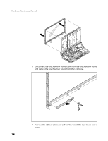
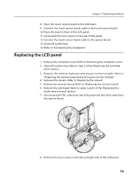
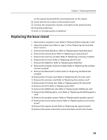
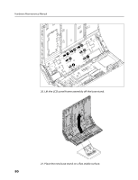
Chapter 7. Replacing hardware 8. Place the touch sensor board to the LCD bezel. 9. Connect the touch sensor board cable to the touch sensor board. 10. Place the bezel in front of the LCD panel. 11. Screw back the nine screws on the rear of the panel. 12. Connect the touch sensor board cable to the system board. 13. Close the system bay. 14. Refer to "Completing the installation". Replacing the LCD panel 1. Remove the computer cover. Refer to "Removing the computer cover". 2. Open the system bay. Refer to step 2 of the "Replacing the hard disk drive" section. 3. Remove the wireless keyboard and mouse receiver module. Refer to "Replacing the wireless keyboard and mouse receiver module". 4. Remove the camera. Refer to "Replacing the camera". 5. Remove the inverter board. Refer to "Replacing the inverter board". 6. Remove the LCD bezel. Refer to steps 4 and 5 of the "Replacing the touch sensor board" section. 7. Disconnect the FPC cable from the LCD panel and the LVDs cable from the system board. 8. Remove the four screws on the left and right side of the LCD panel. 75
-
 1
1 -
2
-
3
-
4
-
5
-
6
-
7
-
8
-
9
-
10
-
11
-
12
-
13
-
14
-
15
-
16
-
17
-
18
-
19
-
20
-
21
-
22
-
23
-
24
-
25
-
26
-
27
-
28
-
29
-
30
-
31
-
32
-
33
-
34
-
35
-
36
-
37
-
38
-
39
-
40
-
41
-
42
-
43
-
44
-
45
-
46
-
47
-
48
-
49
-
50
-
51
-
52
-
53
-
54
-
55
-
56
-
57
-
58
-
59
-
60
-
61
-
62
-
63
-
64
-
65
-
66
-
67
-
68
-
69
-
70
-
71
-
 72
72 -
 73
73 -
 74
74 -
 75
75 -
 76
76 -
 77
77 -
 78
78 -
 79
79 -
 80
80 -
 81
81 -
 82
82 -
83
-
84
-
85
-
86
-
87
-
88
-
89
-
90
-
91
 |
 |
