Lenovo A600 Lenovo IdeaCentre A600 Hardware Maintenance Manual - Page 81
Replacing the base stand
 |
UPC - 884942547713
View all Lenovo A600 manuals
Add to My Manuals
Save this manual to your list of manuals |
Page 81 highlights
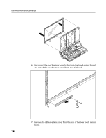
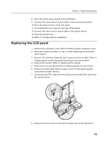
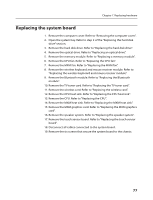
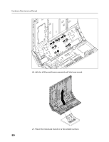
Chapter 7. Replacing hardware on the system board with the mounting holes on the chassis. 22. Screw back the six screws on the system board. 23. Connect all components, boards, and cables to the system board. 24. Close the system bay. 25. Refer to "Completing the installation". Replacing the base stand 1. Remove the computer cover. Refer to "Removing the computer cover". 2. Open the system bay. Refer to step 2 of the "Replacing the hard disk drive" section. 3. Remove the hard disk drive. Refer to "Replacing the hard disk drive". 4. Remove the optical drive. Refer to "Replacing an optical drive". 5. Remove the memory module. Refer to "Replacing a memory module". 6. Remove the CPU fan. Refer to "Replacing the CPU fan". 7. Remove the MXM fan. Refer to "Replacing the MXM fan". 8. Remove the wireless receiver module. Refer to "Replacing the wireless receiver module". 9. Remove the Bluetooth module. Refer to "Replacing the Bluetooth module". 10. Remove the TV tuner card. Refer to "Replacing the TV tuner card". 11. Remove the wireless card. Refer to "Replacing the wireless card". 12. Remove the CPU heat sink. Refer to "Replacing the CPU heat sink". 13. Remove the CPU. Refer to "Replacing the CPU". 14. Remove the MXM heat sink. Refer to "Replacing the MXM heat sink". 15. Remove the MXM graphics card. Refer to "Replacing the MXM graphics card". 16. Remove the speaker system. Refer to "Replacing the speaker system". 17. Remove the touch sensor board. Refer to "Replacing the touch sensor board". 18. Remove the system board. Refer to "Replacing the system board". 19. Remove the seven screws that secure the base stand to the chassis. 79
-
 1
1 -
2
-
3
-
4
-
5
-
6
-
7
-
8
-
9
-
10
-
11
-
12
-
13
-
14
-
15
-
16
-
17
-
18
-
19
-
20
-
21
-
22
-
23
-
24
-
25
-
26
-
27
-
28
-
29
-
30
-
31
-
32
-
33
-
34
-
35
-
36
-
37
-
38
-
39
-
40
-
41
-
42
-
43
-
44
-
45
-
46
-
47
-
48
-
49
-
50
-
51
-
52
-
53
-
54
-
55
-
56
-
57
-
58
-
59
-
60
-
61
-
62
-
63
-
64
-
65
-
66
-
67
-
68
-
69
-
70
-
71
-
72
-
73
-
74
-
75
-
 76
76 -
 77
77 -
 78
78 -
 79
79 -
 80
80 -
 81
81 -
 82
82 -
 83
83 -
 84
84 -
 85
85 -
 86
86 -
87
-
88
-
89
-
90
-
91
 |
 |
