Lenovo ThinkCentre M50e Hardware Maintenance Manual - Page 105
Removing, replacing, system, board, microprocessor
 |
View all Lenovo ThinkCentre M50e manuals
Add to My Manuals
Save this manual to your list of manuals |
Page 105 highlights
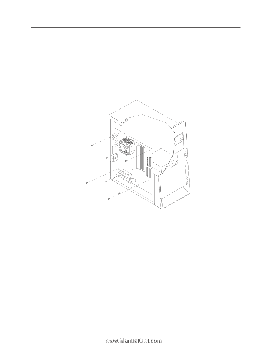
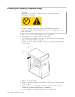
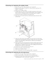
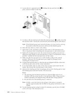
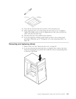
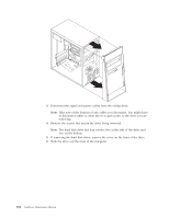
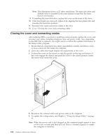
Removing and replacing the system board 1. Remove the cover. See "Removing the cover" on page 92. 2. Remove any PCI adapters installed. See "Removing and replacing a PCI adapter" on page 96. 3. Remove any air baffles or ducts. 4. Carefully take note of the location of all cable connections on the system board. It will be necessary to reconnect them properly when installing a new system board. See "Identifying parts on the system board" on page 95. 5. Disconnect all cables connected to the system board. 6. Remove the screws that secure the system board in place and remove the system board. 7. Take note of the location of the DIMMs and remove them from the failing system board and install them on the new system board in the same location as they were on the failing system board. See "Removing and replacing memory" on page 96. 8. Remove the heat sink and microprocessor from the failing system board and install them on the new system board. See "Removing and replacing the microprocessor." Continue at the next step after installing the heat sink and microprocessor on the new system board. 9. Install the new system board and insert the screws. 10. Reconnect all cables to the system board. 11. Replace any air baffles or ducts. 12. Go to "Closing the cover and connecting cables" on page 104. Removing and replacing the microprocessor 1. Remove the cover. See "Removing the cover" on page 92. 2. Remove any air baffles or ducts that cover the microprocessor. 3. Disconnect the heat sink fan cable from the system board. Refer to "Identifying parts on the system board" on page 95. Chapter 8. Replacing FRUs (Types 8126, 8174, 8175, and 8176) 99
-
 1
1 -
2
-
3
-
4
-
5
-
6
-
7
-
8
-
9
-
10
-
11
-
12
-
13
-
14
-
15
-
16
-
17
-
18
-
19
-
20
-
21
-
22
-
23
-
24
-
25
-
26
-
27
-
28
-
29
-
30
-
31
-
32
-
33
-
34
-
35
-
36
-
37
-
38
-
39
-
40
-
41
-
42
-
43
-
44
-
45
-
46
-
47
-
48
-
49
-
50
-
51
-
52
-
53
-
54
-
55
-
56
-
57
-
58
-
59
-
60
-
61
-
62
-
63
-
64
-
65
-
66
-
67
-
68
-
69
-
70
-
71
-
72
-
73
-
74
-
75
-
76
-
77
-
78
-
79
-
80
-
81
-
82
-
83
-
84
-
85
-
86
-
87
-
88
-
89
-
90
-
91
-
92
-
93
-
94
-
95
-
96
-
97
-
98
-
99
-
 100
100 -
 101
101 -
 102
102 -
 103
103 -
 104
104 -
 105
105 -
 106
106 -
 107
107 -
 108
108 -
 109
109 -
 110
110 -
111
-
112
-
113
-
114
-
115
-
116
-
117
-
118
-
119
-
120
-
121
-
122
-
123
-
124
-
125
-
126
-
127
-
128
-
129
-
130
-
131
-
132
-
133
-
134
-
135
-
136
-
137
-
138
-
139
-
140
-
141
-
142
-
143
-
144
-
145
-
146
-
147
-
148
-
149
-
150
-
151
-
152
-
153
-
154
-
155
-
156
-
157
-
158
-
159
-
160
-
161
-
162
-
163
-
164
-
165
-
166
-
167
-
168
-
169
-
170
-
171
-
172
-
173
-
174
-
175
-
176
-
177
-
178
-
179
-
180
-
181
-
182
-
183
-
184
-
185
-
186
-
187
-
188
-
189
-
190
-
191
-
192
-
193
-
194
-
195
-
196
-
197
-
198
-
199
-
200
-
201
-
202
-
203
-
204
-
205
-
206
-
207
-
208
-
209
-
210
-
211
-
212
-
213
-
214
-
215
-
216
-
217
-
218
-
219
-
220
-
221
-
222
-
223
-
224
-
225
-
226
-
227
-
228
 |
 |