Lenovo ThinkCentre M50e Hardware Maintenance Manual - Page 118
Removing, replacing, system, board
 |
View all Lenovo ThinkCentre M50e manuals
Add to My Manuals
Save this manual to your list of manuals |
Page 118 highlights
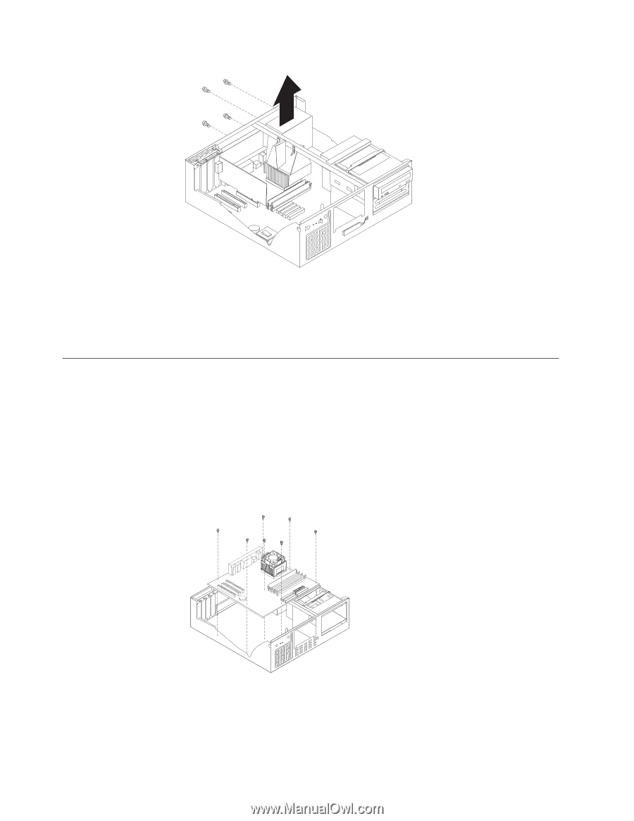
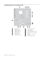
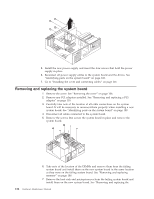
5. Install the new power supply and insert the four screws that hold the power supply in place. 6. Reconnect all power supply cables to the system board and the drives. See "Identifying parts on the system board" on page 108. 7. Go to "Installing the cover and connecting cables" on page 116. Removing and replacing the system board 1. Remove the cover. See "Removing the cover" on page 106. 2. Remove any PCI adapters installed. See "Removing and replacing a PCI adapter" on page 110. 3. Carefully take note of the location of all cable connections on the system board. It will be necessary to reconnect them properly when installing a new system board. See "Identifying parts on the system board" on page 108. 4. Disconnect all cables connected to the system board. 5. Remove the screws that secure the system board in place and remove the system board. 6. Take note of the location of the DIMMs and remove them from the failing system board and install them on the new system board in the same location as they were on the failing system board. See "Removing and replacing memory" on page 109. 7. Remove the heat sink and microprocessor from the failing system board and install them on the new system board. See "Removing and replacing the 112 Hardware Maintenance Manual
-
 1
1 -
2
-
3
-
4
-
5
-
6
-
7
-
8
-
9
-
10
-
11
-
12
-
13
-
14
-
15
-
16
-
17
-
18
-
19
-
20
-
21
-
22
-
23
-
24
-
25
-
26
-
27
-
28
-
29
-
30
-
31
-
32
-
33
-
34
-
35
-
36
-
37
-
38
-
39
-
40
-
41
-
42
-
43
-
44
-
45
-
46
-
47
-
48
-
49
-
50
-
51
-
52
-
53
-
54
-
55
-
56
-
57
-
58
-
59
-
60
-
61
-
62
-
63
-
64
-
65
-
66
-
67
-
68
-
69
-
70
-
71
-
72
-
73
-
74
-
75
-
76
-
77
-
78
-
79
-
80
-
81
-
82
-
83
-
84
-
85
-
86
-
87
-
88
-
89
-
90
-
91
-
92
-
93
-
94
-
95
-
96
-
97
-
98
-
99
-
100
-
101
-
102
-
103
-
104
-
105
-
106
-
107
-
108
-
109
-
110
-
111
-
112
-
 113
113 -
 114
114 -
 115
115 -
 116
116 -
 117
117 -
 118
118 -
 119
119 -
 120
120 -
 121
121 -
 122
122 -
 123
123 -
124
-
125
-
126
-
127
-
128
-
129
-
130
-
131
-
132
-
133
-
134
-
135
-
136
-
137
-
138
-
139
-
140
-
141
-
142
-
143
-
144
-
145
-
146
-
147
-
148
-
149
-
150
-
151
-
152
-
153
-
154
-
155
-
156
-
157
-
158
-
159
-
160
-
161
-
162
-
163
-
164
-
165
-
166
-
167
-
168
-
169
-
170
-
171
-
172
-
173
-
174
-
175
-
176
-
177
-
178
-
179
-
180
-
181
-
182
-
183
-
184
-
185
-
186
-
187
-
188
-
189
-
190
-
191
-
192
-
193
-
194
-
195
-
196
-
197
-
198
-
199
-
200
-
201
-
202
-
203
-
204
-
205
-
206
-
207
-
208
-
209
-
210
-
211
-
212
-
213
-
214
-
215
-
216
-
217
-
218
-
219
-
220
-
221
-
222
-
223
-
224
-
225
-
226
-
227
-
228
 |
 |