Lenovo ThinkCentre M50e Hardware Maintenance Manual - Page 119
Removing, replacing, microprocessor
 |
View all Lenovo ThinkCentre M50e manuals
Add to My Manuals
Save this manual to your list of manuals |
Page 119 highlights
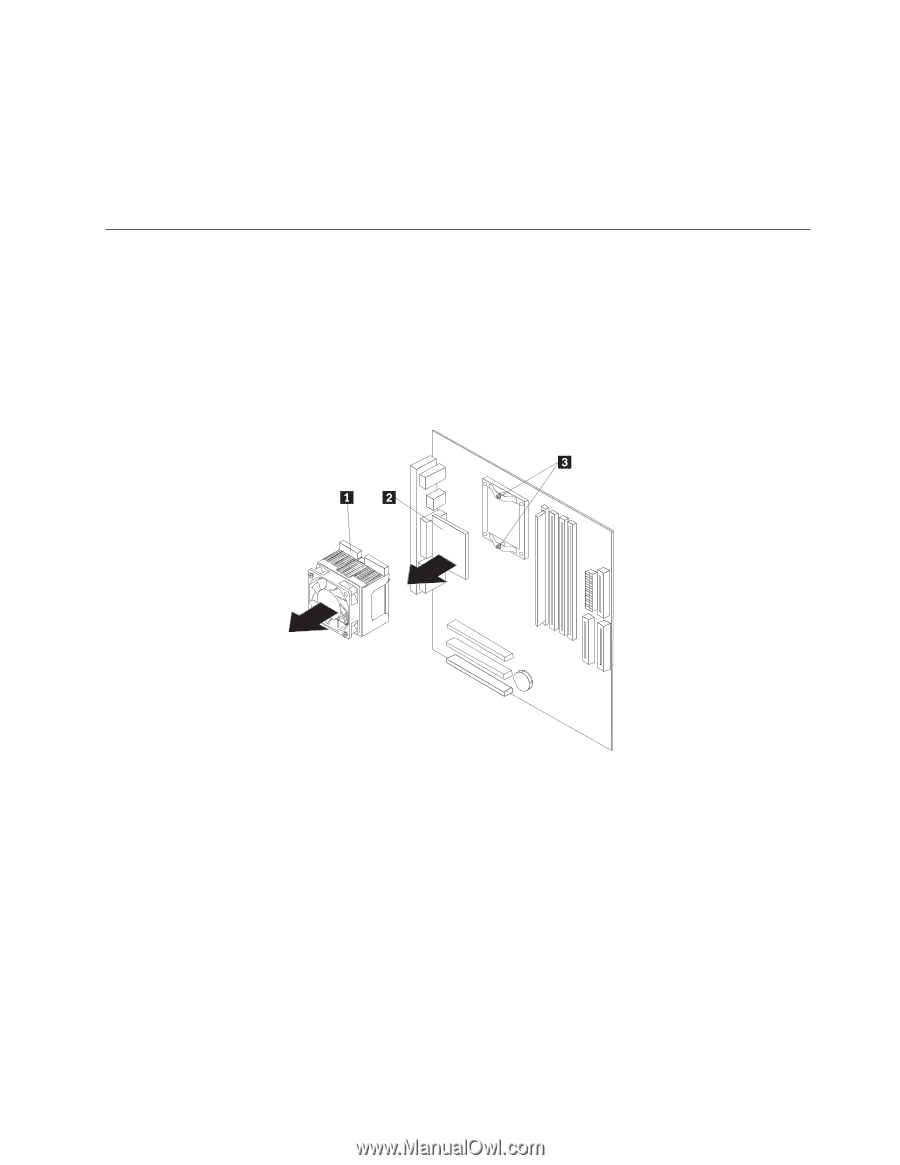
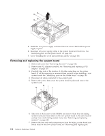
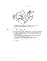
microprocessor." Continue to the next step after installing the heat sink and microprocessor on the new system board. 8. Install the new system board into the chassis and insert the screws. 9. Reconnect all cables to the system board. See "Identifying parts on the system board" on page 108. 10. Go to "Installing the cover and connecting cables" on page 116. Removing and replacing the microprocessor 1. Turn off the computer and peripheral devices and disconnect all external cables and power cords; then, remove the cover. See "Removing the cover" on page 106. 2. Remove any air baffles or ducts that cover the microprocessor. 3. Disconnect the heat sink fan cable from the system board. Refer to "Identifying parts on the system board" on page 108. 4. Loosen the two captured screws 3 holding the fan and heat sink in place, and pivot them to the side. 5. To remove the fan and heat sink 1 from the microprocessor 2 , gently twist the fan and heat sink to break the seal formed by the thermal grease and remove. Note: If the thermal grease seal cannot be broken, you may want to start up the system to heat the processor and loosen the thermal grease. 6. Place the heat sink on a clean work surface. 7. Take notice of the orientation of the beveled corner on the microprocessor. This is important when reinstalling the microprocessor on the system board. 8. Release the microprocessor from the system board by pulling outward and lifting the small handle on the microprocessor socket to its maximum vertical position. Carefully lift the microprocessor off the socket. 9. Make sure that the microprocessor socket handle is fully in the vertical position. Otherwise the microprocessor pins might be damaged when installing the microprocessor. 10. Position the microprocessor so that the pins are aligned with the socket and with the beveled corner in the correct orientation. Chapter 9. Replacing FRUs (Types 8149, 8177, and 8178) 113
-
 1
1 -
2
-
3
-
4
-
5
-
6
-
7
-
8
-
9
-
10
-
11
-
12
-
13
-
14
-
15
-
16
-
17
-
18
-
19
-
20
-
21
-
22
-
23
-
24
-
25
-
26
-
27
-
28
-
29
-
30
-
31
-
32
-
33
-
34
-
35
-
36
-
37
-
38
-
39
-
40
-
41
-
42
-
43
-
44
-
45
-
46
-
47
-
48
-
49
-
50
-
51
-
52
-
53
-
54
-
55
-
56
-
57
-
58
-
59
-
60
-
61
-
62
-
63
-
64
-
65
-
66
-
67
-
68
-
69
-
70
-
71
-
72
-
73
-
74
-
75
-
76
-
77
-
78
-
79
-
80
-
81
-
82
-
83
-
84
-
85
-
86
-
87
-
88
-
89
-
90
-
91
-
92
-
93
-
94
-
95
-
96
-
97
-
98
-
99
-
100
-
101
-
102
-
103
-
104
-
105
-
106
-
107
-
108
-
109
-
110
-
111
-
112
-
113
-
 114
114 -
 115
115 -
 116
116 -
 117
117 -
 118
118 -
 119
119 -
 120
120 -
 121
121 -
 122
122 -
 123
123 -
 124
124 -
125
-
126
-
127
-
128
-
129
-
130
-
131
-
132
-
133
-
134
-
135
-
136
-
137
-
138
-
139
-
140
-
141
-
142
-
143
-
144
-
145
-
146
-
147
-
148
-
149
-
150
-
151
-
152
-
153
-
154
-
155
-
156
-
157
-
158
-
159
-
160
-
161
-
162
-
163
-
164
-
165
-
166
-
167
-
168
-
169
-
170
-
171
-
172
-
173
-
174
-
175
-
176
-
177
-
178
-
179
-
180
-
181
-
182
-
183
-
184
-
185
-
186
-
187
-
188
-
189
-
190
-
191
-
192
-
193
-
194
-
195
-
196
-
197
-
198
-
199
-
200
-
201
-
202
-
203
-
204
-
205
-
206
-
207
-
208
-
209
-
210
-
211
-
212
-
213
-
214
-
215
-
216
-
217
-
218
-
219
-
220
-
221
-
222
-
223
-
224
-
225
-
226
-
227
-
228
 |
 |