Lenovo ThinkCentre M50e Hardware Maintenance Manual - Page 110
Closing, cover, connecting, cables
 |
View all Lenovo ThinkCentre M50e manuals
Add to My Manuals
Save this manual to your list of manuals |
Page 110 highlights
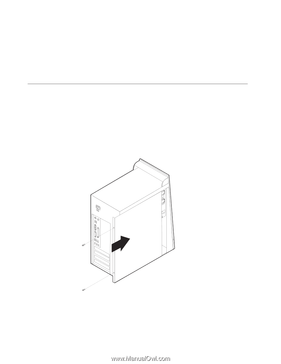
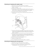
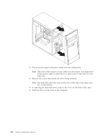
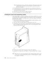
Note: This illustration shows a CD drive installation. The hard disk drive and diskette drive is installed in the same manner except that the front bezel is not in place. 9. If installing the hard disk drive, replace the cover on the front of the drive. 10. If the front bezel was removed, replace it by aligning the four plastic tabs and pressing the bezel into position. 11. Reconnect the signal and power cables to the drive. 12. Go to "Closing the cover and connecting cables." Closing the cover and connecting cables After replacing FRUs, you need to install any removed parts, replace the cover, and reconnect any cables, including telephone lines and power cords. Also, depending on the FRU that is replaced, you might need to confirm the updated information in the Setup Utility program. 1. Ensure that all components have been reassembled correctly and that no tools or loose screws are left inside the computer. 2. Clear any cables that might impede the replacement of the cover. 3. Position the cover on the chassis so that the guides on the top and bottom of the cover engage the chassis and push the cover to the closed position. Insert the screws that secure the cover. 4. Reconnect the external cables and power cords to the computer. 5. To update the configuration, see Chapter 6, "Using the Setup Utility," on page 55. Note: When the power cord is first plugged in, the computer might appear to turn on for a few seconds and then turn off. This is a normal sequence to enable the computer to initialize. 104 Hardware Maintenance Manual
-
 1
1 -
2
-
3
-
4
-
5
-
6
-
7
-
8
-
9
-
10
-
11
-
12
-
13
-
14
-
15
-
16
-
17
-
18
-
19
-
20
-
21
-
22
-
23
-
24
-
25
-
26
-
27
-
28
-
29
-
30
-
31
-
32
-
33
-
34
-
35
-
36
-
37
-
38
-
39
-
40
-
41
-
42
-
43
-
44
-
45
-
46
-
47
-
48
-
49
-
50
-
51
-
52
-
53
-
54
-
55
-
56
-
57
-
58
-
59
-
60
-
61
-
62
-
63
-
64
-
65
-
66
-
67
-
68
-
69
-
70
-
71
-
72
-
73
-
74
-
75
-
76
-
77
-
78
-
79
-
80
-
81
-
82
-
83
-
84
-
85
-
86
-
87
-
88
-
89
-
90
-
91
-
92
-
93
-
94
-
95
-
96
-
97
-
98
-
99
-
100
-
101
-
102
-
103
-
104
-
 105
105 -
 106
106 -
 107
107 -
 108
108 -
 109
109 -
 110
110 -
 111
111 -
 112
112 -
 113
113 -
 114
114 -
 115
115 -
116
-
117
-
118
-
119
-
120
-
121
-
122
-
123
-
124
-
125
-
126
-
127
-
128
-
129
-
130
-
131
-
132
-
133
-
134
-
135
-
136
-
137
-
138
-
139
-
140
-
141
-
142
-
143
-
144
-
145
-
146
-
147
-
148
-
149
-
150
-
151
-
152
-
153
-
154
-
155
-
156
-
157
-
158
-
159
-
160
-
161
-
162
-
163
-
164
-
165
-
166
-
167
-
168
-
169
-
170
-
171
-
172
-
173
-
174
-
175
-
176
-
177
-
178
-
179
-
180
-
181
-
182
-
183
-
184
-
185
-
186
-
187
-
188
-
189
-
190
-
191
-
192
-
193
-
194
-
195
-
196
-
197
-
198
-
199
-
200
-
201
-
202
-
203
-
204
-
205
-
206
-
207
-
208
-
209
-
210
-
211
-
212
-
213
-
214
-
215
-
216
-
217
-
218
-
219
-
220
-
221
-
222
-
223
-
224
-
225
-
226
-
227
-
228
 |
 |