Lenovo ThinkCentre M50e Hardware Maintenance Manual - Page 135
installing
 |
View all Lenovo ThinkCentre M50e manuals
Add to My Manuals
Save this manual to your list of manuals |
Page 135 highlights
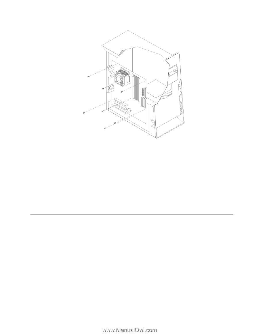
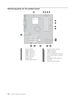
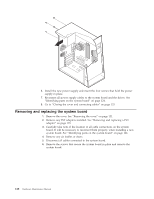
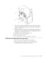
7. Take note of the location of the DIMMs and remove them from the failing system board and install them on the new system board in the same location as they were on the failing system board. See "Removing and replacing memory" on page 125. 8. Remove the heat sink and microprocessor from the failing system board and install them on the new system board. See "Removing and replacing the microprocessor." Continue at the next step after installing the heat sink and microprocessor on the new system board. 9. Install the new system board and insert the screws. 10. Reconnect all cables to the system board. 11. Replace any air baffles or ducts. 12. Go to "Closing the cover and connecting cables" on page 133. Removing and replacing the microprocessor 1. Remove the cover. See "Removing the cover" on page 121. 2. Remove any air baffles or ducts that cover the microprocessor. 3. Disconnect the heat sink fan cable from the system board. Refer to "Identifying parts on the system board" on page 124. Chapter 10. Replacing FRUs (Types 8084, 8085, 8147, 8148, and 8179 129
-
 1
1 -
2
-
3
-
4
-
5
-
6
-
7
-
8
-
9
-
10
-
11
-
12
-
13
-
14
-
15
-
16
-
17
-
18
-
19
-
20
-
21
-
22
-
23
-
24
-
25
-
26
-
27
-
28
-
29
-
30
-
31
-
32
-
33
-
34
-
35
-
36
-
37
-
38
-
39
-
40
-
41
-
42
-
43
-
44
-
45
-
46
-
47
-
48
-
49
-
50
-
51
-
52
-
53
-
54
-
55
-
56
-
57
-
58
-
59
-
60
-
61
-
62
-
63
-
64
-
65
-
66
-
67
-
68
-
69
-
70
-
71
-
72
-
73
-
74
-
75
-
76
-
77
-
78
-
79
-
80
-
81
-
82
-
83
-
84
-
85
-
86
-
87
-
88
-
89
-
90
-
91
-
92
-
93
-
94
-
95
-
96
-
97
-
98
-
99
-
100
-
101
-
102
-
103
-
104
-
105
-
106
-
107
-
108
-
109
-
110
-
111
-
112
-
113
-
114
-
115
-
116
-
117
-
118
-
119
-
120
-
121
-
122
-
123
-
124
-
125
-
126
-
127
-
128
-
129
-
 130
130 -
 131
131 -
 132
132 -
 133
133 -
 134
134 -
 135
135 -
 136
136 -
 137
137 -
 138
138 -
 139
139 -
 140
140 -
141
-
142
-
143
-
144
-
145
-
146
-
147
-
148
-
149
-
150
-
151
-
152
-
153
-
154
-
155
-
156
-
157
-
158
-
159
-
160
-
161
-
162
-
163
-
164
-
165
-
166
-
167
-
168
-
169
-
170
-
171
-
172
-
173
-
174
-
175
-
176
-
177
-
178
-
179
-
180
-
181
-
182
-
183
-
184
-
185
-
186
-
187
-
188
-
189
-
190
-
191
-
192
-
193
-
194
-
195
-
196
-
197
-
198
-
199
-
200
-
201
-
202
-
203
-
204
-
205
-
206
-
207
-
208
-
209
-
210
-
211
-
212
-
213
-
214
-
215
-
216
-
217
-
218
-
219
-
220
-
221
-
222
-
223
-
224
-
225
-
226
-
227
-
228
 |
 |