Lenovo ThinkCentre M50e Hardware Maintenance Manual - Page 137
disconnect.
 |
View all Lenovo ThinkCentre M50e manuals
Add to My Manuals
Save this manual to your list of manuals |
Page 137 highlights
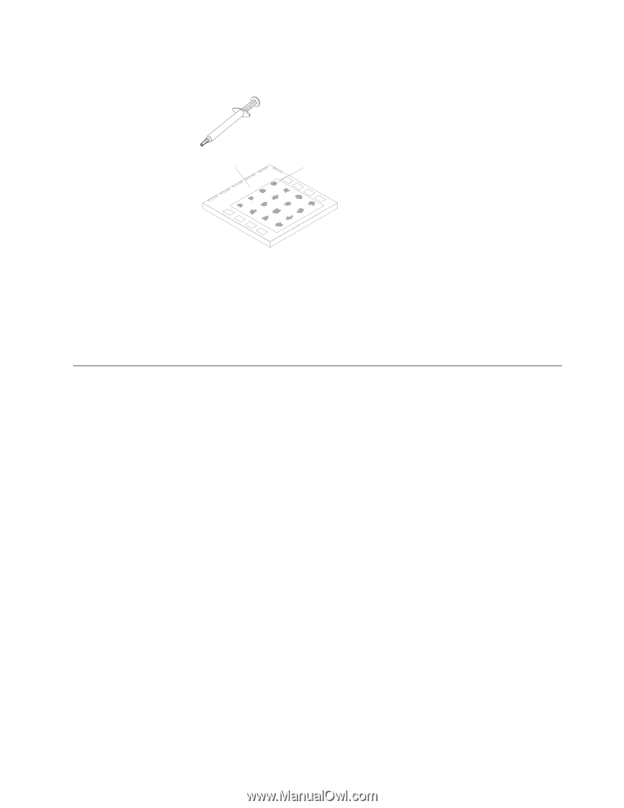
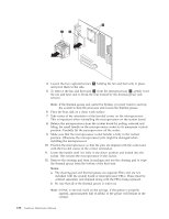
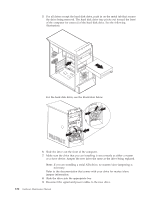
13. Use the thermal grease syringe to place 16 uniformly spaced dots of 0.01ML each on the top of the microprocessor. Microprocessor 0.01 mL of thermal grease 14. Place the fan and heat sink into position on the microprocessor. 15. When tightening the screws that clamp the heat sink, do not overtighten. Tighten the clamp screws evenly by tightening one side some and then the other until they are both snug. 16. Reconnect the fan to the system board connector. 17. Replace any air baffles or ducts. 18. Go to "Closing the cover and connecting cables" on page 133. Removing and replacing drives 1. Remove the cover. See "Removing the cover" on page 121. 2. If you are removing a drive from bay 1 or bay 2, skip the next step. 3. Remove the front bezel by pushing in on the blue plastic tab at the rear of the chassis. 4. Disconnect the signal and power cables from the drive being removed. Note: Take note of the location of any cables you disconnect. You might have to disconnect cables to other drives to gain access to the drive you are removing. Chapter 10. Replacing FRUs (Types 8084, 8085, 8147, 8148, and 8179 131
-
 1
1 -
2
-
3
-
4
-
5
-
6
-
7
-
8
-
9
-
10
-
11
-
12
-
13
-
14
-
15
-
16
-
17
-
18
-
19
-
20
-
21
-
22
-
23
-
24
-
25
-
26
-
27
-
28
-
29
-
30
-
31
-
32
-
33
-
34
-
35
-
36
-
37
-
38
-
39
-
40
-
41
-
42
-
43
-
44
-
45
-
46
-
47
-
48
-
49
-
50
-
51
-
52
-
53
-
54
-
55
-
56
-
57
-
58
-
59
-
60
-
61
-
62
-
63
-
64
-
65
-
66
-
67
-
68
-
69
-
70
-
71
-
72
-
73
-
74
-
75
-
76
-
77
-
78
-
79
-
80
-
81
-
82
-
83
-
84
-
85
-
86
-
87
-
88
-
89
-
90
-
91
-
92
-
93
-
94
-
95
-
96
-
97
-
98
-
99
-
100
-
101
-
102
-
103
-
104
-
105
-
106
-
107
-
108
-
109
-
110
-
111
-
112
-
113
-
114
-
115
-
116
-
117
-
118
-
119
-
120
-
121
-
122
-
123
-
124
-
125
-
126
-
127
-
128
-
129
-
130
-
131
-
 132
132 -
 133
133 -
 134
134 -
 135
135 -
 136
136 -
 137
137 -
 138
138 -
 139
139 -
 140
140 -
 141
141 -
 142
142 -
143
-
144
-
145
-
146
-
147
-
148
-
149
-
150
-
151
-
152
-
153
-
154
-
155
-
156
-
157
-
158
-
159
-
160
-
161
-
162
-
163
-
164
-
165
-
166
-
167
-
168
-
169
-
170
-
171
-
172
-
173
-
174
-
175
-
176
-
177
-
178
-
179
-
180
-
181
-
182
-
183
-
184
-
185
-
186
-
187
-
188
-
189
-
190
-
191
-
192
-
193
-
194
-
195
-
196
-
197
-
198
-
199
-
200
-
201
-
202
-
203
-
204
-
205
-
206
-
207
-
208
-
209
-
210
-
211
-
212
-
213
-
214
-
215
-
216
-
217
-
218
-
219
-
220
-
221
-
222
-
223
-
224
-
225
-
226
-
227
-
228
 |
 |