Lenovo ThinkCentre M50e Hardware Maintenance Manual - Page 112
Important
 |
View all Lenovo ThinkCentre M50e manuals
Add to My Manuals
Save this manual to your list of manuals |
Page 112 highlights
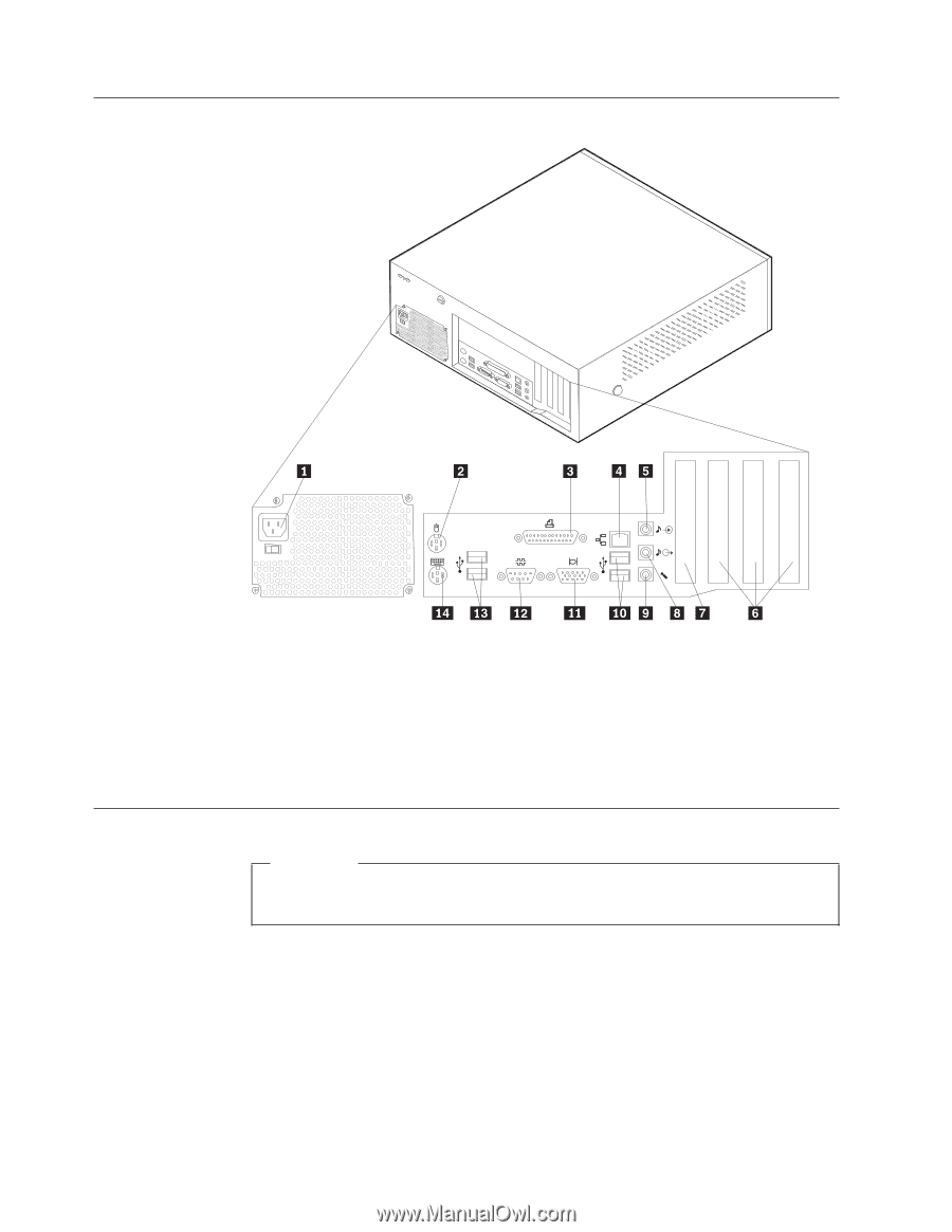
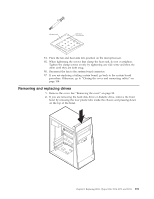
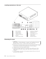
Locating connectors on the rear 1 Power connector 2 Mouse connector 3 Parallel connector 4 Ethernet connector 5 Audio line in connector 6 PCI slots 7 AGP slot (some models) 8 Audio line out connector 9 Microphone connector 10 USB connectors 11 VGA monitor connector 12 Serial connector 13 USB connectors 14 Keyboard connector Removing the cover Important Read Chapter 2, "Safety information," on page 5 and "Handling electrostatic discharge-sensitive devices" on page 8 before removing the cover. 1. Shut down your operating system, remove any media (diskettes, CDs, or tapes) from the drives, and turn off all attached devices and the computer. 2. Unplug all power cords from electrical outlets. 3. Disconnect all cables attached to the computer. This includes power cords, input/output (I/O) cables, and any other cables that are connected to the computer. 4. Press the buttons on the sides of the computer and pivot the rear of the cover up and off of the computer. 106 Hardware Maintenance Manual
-
 1
1 -
2
-
3
-
4
-
5
-
6
-
7
-
8
-
9
-
10
-
11
-
12
-
13
-
14
-
15
-
16
-
17
-
18
-
19
-
20
-
21
-
22
-
23
-
24
-
25
-
26
-
27
-
28
-
29
-
30
-
31
-
32
-
33
-
34
-
35
-
36
-
37
-
38
-
39
-
40
-
41
-
42
-
43
-
44
-
45
-
46
-
47
-
48
-
49
-
50
-
51
-
52
-
53
-
54
-
55
-
56
-
57
-
58
-
59
-
60
-
61
-
62
-
63
-
64
-
65
-
66
-
67
-
68
-
69
-
70
-
71
-
72
-
73
-
74
-
75
-
76
-
77
-
78
-
79
-
80
-
81
-
82
-
83
-
84
-
85
-
86
-
87
-
88
-
89
-
90
-
91
-
92
-
93
-
94
-
95
-
96
-
97
-
98
-
99
-
100
-
101
-
102
-
103
-
104
-
105
-
106
-
 107
107 -
 108
108 -
 109
109 -
 110
110 -
 111
111 -
 112
112 -
 113
113 -
 114
114 -
 115
115 -
 116
116 -
 117
117 -
118
-
119
-
120
-
121
-
122
-
123
-
124
-
125
-
126
-
127
-
128
-
129
-
130
-
131
-
132
-
133
-
134
-
135
-
136
-
137
-
138
-
139
-
140
-
141
-
142
-
143
-
144
-
145
-
146
-
147
-
148
-
149
-
150
-
151
-
152
-
153
-
154
-
155
-
156
-
157
-
158
-
159
-
160
-
161
-
162
-
163
-
164
-
165
-
166
-
167
-
168
-
169
-
170
-
171
-
172
-
173
-
174
-
175
-
176
-
177
-
178
-
179
-
180
-
181
-
182
-
183
-
184
-
185
-
186
-
187
-
188
-
189
-
190
-
191
-
192
-
193
-
194
-
195
-
196
-
197
-
198
-
199
-
200
-
201
-
202
-
203
-
204
-
205
-
206
-
207
-
208
-
209
-
210
-
211
-
212
-
213
-
214
-
215
-
216
-
217
-
218
-
219
-
220
-
221
-
222
-
223
-
224
-
225
-
226
-
227
-
228
 |
 |