Lenovo ThinkCentre M50e Hardware Maintenance Manual - Page 131
connectors.
 |
View all Lenovo ThinkCentre M50e manuals
Add to My Manuals
Save this manual to your list of manuals |
Page 131 highlights
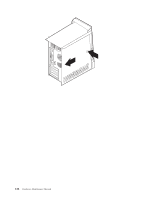
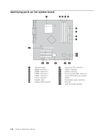
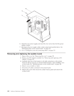
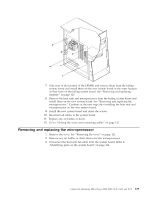
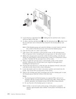
Removing and replacing memory 1. Remove the cover. See "Removing the cover" on page 121. 2. To locate the DIMM connectors. See "Identifying parts on the system board" on page 124. 3. Open the retaining clips and remove the failing DIMM. 4. Make sure the notch 1 on the new DIMM is aligned correctly with the connector key 2 on the socket. Insert the DIMM straight down into the connector until it snaps into position and the retaining clips are closed. 5. Go to "Closing the cover and connecting cables" on page 133. Removing and replacing a PCI adapter 1. Remove the cover. See "Removing the cover" on page 121. Chapter 10. Replacing FRUs (Types 8084, 8085, 8147, 8148, and 8179 125
-
 1
1 -
2
-
3
-
4
-
5
-
6
-
7
-
8
-
9
-
10
-
11
-
12
-
13
-
14
-
15
-
16
-
17
-
18
-
19
-
20
-
21
-
22
-
23
-
24
-
25
-
26
-
27
-
28
-
29
-
30
-
31
-
32
-
33
-
34
-
35
-
36
-
37
-
38
-
39
-
40
-
41
-
42
-
43
-
44
-
45
-
46
-
47
-
48
-
49
-
50
-
51
-
52
-
53
-
54
-
55
-
56
-
57
-
58
-
59
-
60
-
61
-
62
-
63
-
64
-
65
-
66
-
67
-
68
-
69
-
70
-
71
-
72
-
73
-
74
-
75
-
76
-
77
-
78
-
79
-
80
-
81
-
82
-
83
-
84
-
85
-
86
-
87
-
88
-
89
-
90
-
91
-
92
-
93
-
94
-
95
-
96
-
97
-
98
-
99
-
100
-
101
-
102
-
103
-
104
-
105
-
106
-
107
-
108
-
109
-
110
-
111
-
112
-
113
-
114
-
115
-
116
-
117
-
118
-
119
-
120
-
121
-
122
-
123
-
124
-
125
-
 126
126 -
 127
127 -
 128
128 -
 129
129 -
 130
130 -
 131
131 -
 132
132 -
 133
133 -
 134
134 -
 135
135 -
 136
136 -
137
-
138
-
139
-
140
-
141
-
142
-
143
-
144
-
145
-
146
-
147
-
148
-
149
-
150
-
151
-
152
-
153
-
154
-
155
-
156
-
157
-
158
-
159
-
160
-
161
-
162
-
163
-
164
-
165
-
166
-
167
-
168
-
169
-
170
-
171
-
172
-
173
-
174
-
175
-
176
-
177
-
178
-
179
-
180
-
181
-
182
-
183
-
184
-
185
-
186
-
187
-
188
-
189
-
190
-
191
-
192
-
193
-
194
-
195
-
196
-
197
-
198
-
199
-
200
-
201
-
202
-
203
-
204
-
205
-
206
-
207
-
208
-
209
-
210
-
211
-
212
-
213
-
214
-
215
-
216
-
217
-
218
-
219
-
220
-
221
-
222
-
223
-
224
-
225
-
226
-
227
-
228
 |
 |
Removing
and
replacing
memory
1.
Remove
the
cover.
See
“Removing
the
cover”
on
page
121.
2.
To
locate
the
DIMM
connectors.
See
“Identifying
parts
on
the
system
board”
on
page
124.
3.
Open
the
retaining
clips
and
remove
the
failing
DIMM.
4.
Make
sure
the
notch
±1²
on
the
new
DIMM
is
aligned
correctly
with
the
connector
key
±2²
on
the
socket.
Insert
the
DIMM
straight
down
into
the
connector
until
it
snaps
into
position
and
the
retaining
clips
are
closed.
5.
Go
to
“Closing
the
cover
and
connecting
cables”
on
page
133.
Removing
and
replacing
a
PCI
adapter
1.
Remove
the
cover.
See
“Removing
the
cover”
on
page
121.
Chapter
10.
Replacing
FRUs
(Types
8084,
8085,
8147,
8148,
and
8179
125