Maytag MEDZ600TB Use and Care Guide - Page 13
to external
 |
UPC - 883049064925
View all Maytag MEDZ600TB manuals
Add to My Manuals
Save this manual to your list of manuals |
Page 13 highlights
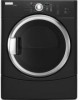
Strip 5" (12.7 cm) of outer covering from end of cable, leaving bare ground wire at 5" (12.7 cm). Cut 11/2" (3.8 cm) from 3 remaining wires. Strip insulation back 1" (2.5 cm). Shape ends of wires into a hook shape.
-
 1
1 -
2
-
3
-
4
-
5
-
6
-
7
-
 8
8 -
 9
9 -
 10
10 -
 11
11 -
 12
12 -
 13
13 -
 14
14 -
 15
15 -
 16
16 -
 17
17 -
 18
18 -
19
-
20
-
21
-
22
-
23
-
24
-
25
-
26
-
27
-
28
-
29
-
30
-
31
-
32
-
33
-
34
-
35
-
36
-
37
-
38
-
39
-
40
-
41
-
42
-
43
-
44
-
45
-
46
-
47
-
48
-
49
-
50
-
51
-
52
-
53
-
54
-
55
-
56
-
57
-
58
-
59
-
60
-
61
-
62
-
63
-
64
-
65
-
66
-
67
-
68
-
69
-
70
-
71
-
72
-
73
-
74
-
75
-
76
-
77
-
78
-
79
-
80
-
81
-
82
-
83
-
84
-
85
-
86
-
87
-
88
-
89
-
90
-
91
-
92
 |
 |

Strip
5" (12.7
cm)
of outer
covering
from
end
of cable,
leaving
bare ground
wire
at 5"
(12.7
cm).
Cut
11/2"(3.8
cm)
from
3 remaining
wires.
Strip
insulation
back
1" (2.5 cm).
Shape
ends
of wires
into
a hook
shape.
<,
3.
Connect
ground
wire
(green
or bare)
of direct
wire
cable
to external
ground
conductor
screw.
Tighten
screw.
(12,
7
When
connecting
to the
terminal
block,
place
the
hooked
end
of the
wire
under
the screw
of
the
terminal
block
(hook
facing
right),
squeeze
hooked
end
together
and
tighten
screw,
as
shown.
I,
2.
Remove
center
silver-colored
terminal
block
screw.
Remove
neutral
ground
wire
from
external
ground
conductor
screw.
Connect
neutral
ground
wire
and
place
the
hooked
end
(hook
facing
right)
of the
neutral
wire
(white
or
center
wire)
cff
direct
wire
cable
under
the
cente'r
_crew
cff
the
terminal
blc_ck
£queeTe
hooked
ends together.
Tighten
screw.
/
A.
£xternal
ground
conductor
screw
B.
Ground
wir_"
(green
or bar_')
of power
supply
cable
C. _"
( 1.9 cm)
UL
listed
strain
relie'f
D.
C_'nter
silver-color_'d
tern'linal
block
scr_'w
E.
Neutral
ground
wir_"
[.
Neutral
wire
twhite
or
cente'r
wh_')
Place
the
hooked
ends
of the
other
direct
wire
cable
wires
under
the
outer
terminal
block
screws
(hooks
facing
right).
Squeeze
hooked
ends
together.
Tighten
screws.
!!
!!
5.
Tighten
strain
relief
screw.
6.
Insert
tab of terminal
block
cover
into
slot
of dryer
rear panel.
Secure
cover
with
hold-
(JOWl]
screw.
7.
You have completed
your
electrical
connection.
Now
go to "Venting
Requirements."
A.
Fxternal
ground
conductor
screw
-
Dotted
line
shows
position
of NEUTRAL
ground
wir_'
before'
being
moved
to
center
silve'r-co/ore'd
terminal
block
scr_'w.
B. C_'nter
silver-colored
terminal
block
scre'w
C. Neutral
ground
wire
D.
Neutral
wire
(white
or center
wire)
E.
!4"
( 1.9 cm)
UL listed
strain
relic4