Panasonic WVCU650 WJSX150 User Guide - Page 12
System Status Table, Moving All the Items
 |
UPC - 791871504277
View all Panasonic WVCU650 manuals
Add to My Manuals
Save this manual to your list of manuals |
Page 12 highlights
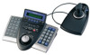
2. Perform desired operations. 2. Press the MENU button repeatedly until "System Status" appears on the LCD. 3. Press the F1 button. The SYSTEM STATUS table will appear on the active monitor as shown in the figure. q Moving the clock display Move the 3D joystick while holding down the F1 button. (1) will move to the desired direction. w Moving the Camera Title Display Move the 3D joystick while holding down the F2 button. (2) will move to the desired direction. e Moving the Event Display Move the 3D joystick while holding down the F3 button. (3) will move to the desired direction. r Moving the Monitor Status* Move the 3D joystick while holding down the F4 button. (4) will move to the desired direction. * Monitor number, controller number and monitor mode ● Moving All the Items 1. Press the MENU button repeatedly until "OSD Position" appears on the LCD. OSD Position 003 Clock Cam Event Mon 2. Hold down the SHIFT button. The LCD display will become as follows. OSD Position 003 All 3. Move the 3D joystick while holding down the F1 button. (1), (2), (3), and (4) (refer to p. 11) will move to the desired position. ■ System Status Table The table shows the current system status. 1. Select the desired monitor. (Refer to p. 3 Monitor Selection.) 12 SYSTEM STATUS MON CAM MODE KB 1 01 T01 K1 2 99 SPOT K2 3 04 ALARM K4 4 R1 RECORDER PC OPE PRI 12345 30 2 2 4 1 30 1 The columns in the table indicate the states as shown in the figure. MON: Monitor number CAM: Logical camera number (01 to 99) Recorder number (R0 to R4)* "- -" indicates that no camera is being selected. MODE: Lists the display mode on the monitors. SPOT: Spot mode Tnn: Tour Sequence mode (nn is the tour sequence number.) CAM: Camera Setup mode SET: WJ-SX150A Setup mode ALARM: Alarm Active mode ACK: Alarm ACK mode VLD H: Video Loss History Table ALM H: Alarm History Table SYS S: System Status Table RECORDER: Recorder mode** KB: Lists the system controller name (K1 to K4) or PSD. OPE: Lists the operator number PRI: Lists the priority number * R0 to R4 shows the following. Recorder number R0 R1 R2 R3 R4 Recorder Master recorder Slave 1 recorder Slave 2 recorder Slave 3 recorder Slave 4 recorder ** When this parameter is selected, a recorder number is displayed in the CAM area. 4. To close the SYSTEM STATUS table, press the F2 button. 5. To exit the mode, press the MON (ESC) button.
-
 1
1 -
2
-
3
-
4
-
5
-
6
-
 7
7 -
 8
8 -
 9
9 -
 10
10 -
 11
11 -
 12
12 -
 13
13 -
 14
14 -
 15
15 -
 16
16 -
 17
17 -
18
-
19
-
20
-
21
-
22
-
23
-
24
-
25
-
26
-
27
-
28
-
29
-
30
-
31
-
32
-
33
-
34
-
35
-
36
-
37
-
38
-
39
-
40
-
41
-
42
-
43
-
44
-
45
-
46
-
47
-
48
 |
 |
