Panasonic WVCU650 WJSX150 User Guide - Page 37
System Connections And Setups (wj-hd300 Series/wj-hd220 Series)
 |
UPC - 791871504277
View all Panasonic WVCU650 manuals
Add to My Manuals
Save this manual to your list of manuals |
Page 37 highlights
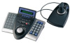
(2) ADDENDUM FOR MATRIX SWITCHER WJ-SX150 SERIES: TO USE DIGITAL DISK RECORDER WJ-HD300 SERIES/WJ-HD220 SERIES SYSTEM CONNECTIONS AND SETUPS (WJ-HD300 SERIES/WJ-HD220 SERIES) ■ Connection with Digital Disk Recorder WJ-HD300 Series Notes: • Refer to service personnel for details on the connection with a recorder to operate via LAN or the Internet. • Check that the firmware of recorder is Ver. 1.30 or later. • Only one recorder can be connected to the DATA HDR connector of this unit. (Multiple unit connections, such as cascade connection, are not available.) ● Basic Connection The following is the description of the connection between a recorder and this unit to confirm the images from the recorder. 1. Set the unit address of the recorder to 1. 2. Set the [Camera control] setting to "PSD" for all cameras in SETUP MENU of the recorder. 3. Connect the unit's CAM OUT 1 to 16 connectors to the recorder's VIDEO IN 1 to 16 connectors with a coaxial cable. 4. Connect the unit's EXT IN connector to the recorder's MULTISCREEN OUT connector with a coaxial cable. 5. Connect the unit's DATA HDR connector to the recorder's DATA port with a modular cable. Notes: • Make sure the recorder's unit address is set to 1 through SETUP MENU or WJ-SX150A administrator Console. (Refer to this unit's operating instructions.) If another number is selected, you cannot control the recorder. • To control cameras at the front panel of recorder, connect the DATA 4 connector and the DATA port of recorder with a modular cable. (PS·Data system controller is not connectable to the DATA 4 connector.) • From system controllers connected to the unit (WJSX150A), you cannot control the monitor connected to the MONITOR OUT 1 connector of recorder. System controller (Terminal Mode) Monitor EXT IN MONITOR OUT ALARM DATA HDR DATA 4 TERM OFF ON SERIAL DATA 3 DATA 2 DATA 1 RS485(CAMERA) LINE 2 SELECT 4 EXT IN (PLAY IN) CAMERA SW IN 3 1 PS•DATA RS485(CAMERA) EXT OUT (REC OUT) 4 2 MONITOR OUT 16 15 14 13 12 11 10 9 8 7 6 5 4 3 2 1 IN OUT 16 15 14 13 12 11 10 9 8 7 6 5 4 3 2 1 CAMERA DATA HDR DATA 4* (PS·Data) SIGNAL GND POWER AC IN Matrix Switcher MONITOR OUT x DATA 3 1 1 SERIAL ALARM 4 2 AUDIO IN AUDIO OUT CASCADE OUT 2 MONITOR OUT CASCADE IN MONITOR (VGA) ALARM/CONTOROL 16 15 14 13 12 11 10 9 8 7 IN OUT 16 15 14 13 12 11 10 9 8 7 VIDEO MODE 2 1 COPY 1 DATA 6 5 RS485(CAMERA) 10/100BASE-T EXT STORAGE 4 3 2 1 6 5 4 3 2 1 SIGNAL GND POWER AC IN Recorder** * Connect these ports if you control cameras from the front panel of recorder. ** Set the recorder's unit address to 1. 37
-
 1
1 -
2
-
3
-
4
-
5
-
6
-
7
-
8
-
9
-
10
-
11
-
12
-
13
-
14
-
15
-
16
-
17
-
18
-
19
-
20
-
21
-
22
-
23
-
24
-
25
-
26
-
27
-
28
-
29
-
30
-
31
-
 32
32 -
 33
33 -
 34
34 -
 35
35 -
 36
36 -
 37
37 -
 38
38 -
 39
39 -
 40
40 -
 41
41 -
 42
42 -
43
-
44
-
45
-
46
-
47
-
48
 |
 |
