Samsung SNB-5000 User Manual - Page 40
Alarm I/O Wiring Diagram
 |
View all Samsung SNB-5000 manuals
Add to My Manuals
Save this manual to your list of manuals |
Page 40 highlights
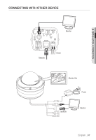
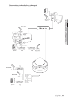
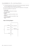
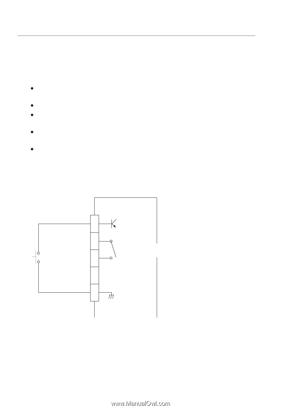
installation & connection 1. Connect the AUDIO IN port of the camera with the microphone directly or LINE OUT port of the amplifier that the microphone is connected to. 2. Connect the AUDIO OUT port of the camera with the LINE IN port of the speaker. 3. Check the specifications for audio input. y Audio Codec G.711 PCM. μ-law 64kbps 8kHz sampling y Full duplex Audio y Audio in Used for mono signal line input (Max.2.4 Vpp) y Audio out Used for mono signal line output (Max.2.4 Vpp) y Line out impedance 600— Alarm I/O Wiring Diagram ALARM IN 1 ALARM OUT 2 ALARM COM 3 4 GND 5 (5mA sink) (30VDC 2A, 125VAC 0.5A MAX) 40_ installation & connection
-
 1
1 -
2
-
3
-
4
-
5
-
6
-
7
-
8
-
9
-
10
-
11
-
12
-
13
-
14
-
15
-
16
-
17
-
18
-
19
-
20
-
21
-
22
-
23
-
24
-
25
-
26
-
27
-
28
-
29
-
30
-
31
-
32
-
33
-
34
-
 35
35 -
 36
36 -
 37
37 -
 38
38 -
 39
39 -
 40
40 -
 41
41 -
 42
42 -
 43
43 -
 44
44 -
 45
45 -
46
-
47
-
48
-
49
-
50
-
51
-
52
-
53
-
54
-
55
-
56
-
57
-
58
-
59
-
60
-
61
-
62
-
63
-
64
-
65
-
66
-
67
-
68
-
69
-
70
-
71
-
72
-
73
-
74
-
75
-
76
-
77
-
78
-
79
-
80
-
81
-
82
-
83
-
84
-
85
-
86
-
87
-
88
-
89
-
90
-
91
-
92
-
93
-
94
-
95
-
96
-
97
-
98
-
99
-
100
-
101
 |
 |
installation & connection
40_
installation & connection
1
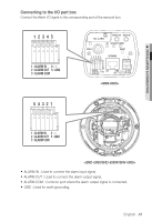
ALARM IN
ALARM OUT
ALARM COM
GND
2
3
4
5
(5mA sink)
(30VDC 2A,
125VAC 0.5A MAX)
Connect the AUDIO IN port of the camera with the microphone directly or LINE OUT
port of the amplifier that the microphone is connected to.
Connect the AUDIO OUT port of the camera with the LINE IN port of the speaker.
Check the specifications for audio input.
Audio Codec
G.711 PCM. μ-law 64kbps 8kHz sampling
Full duplex Audio
Audio in
Used for mono signal line input (Max.2.4 Vpp)
Audio out
Used for mono signal line output (Max.2.4 Vpp)
Line out impedance
600±
Alarm I/O Wiring Diagram
1.
2.
3.