Sony RDR GX257 Operating Instructions - Page 14
Step 3: Connecting the Audio Cords/HDMI Cord - dvd
 |
UPC - 027242731318
View all Sony RDR GX257 manuals
Add to My Manuals
Save this manual to your list of manuals |
Page 14 highlights
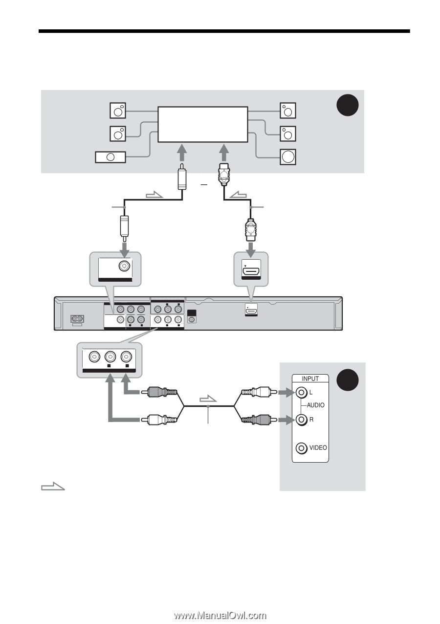
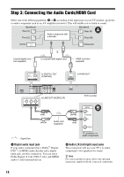
Step 3: Connecting the Audio Cords/HDMI Cord Select one of the following patterns, A or B, according to the input jack on your TV monitor, projector, or audio component such as an AV amplifier (receiver). This will enable you to listen to sound. [Speakers] Rear (L) Front (L) Audio component with a decoder [Speakers] A Rear (R) Front (R) Center Subwoofer or Coaxial digital cord (not supplied) to coaxial/HDMI digital input HDMI cord (not supplied) PCM/DTS/ MPEG/ DOLBY DIGITAL COAXIAL DIGITAL OUT to DIGITAL OUT (COAXIAL) HDMI OUT to HDMI OUT ~AC IN COMPONENT Y VIDEO OUT PB PR PCM/DTS/ MPEG/ DOLBY DIGITAL COAXIAL DIGITAL OUT L - AUDIO - R AUDIO OUT VIDEO LINE 1 IN L - AUDIO - R SET TOP BOX CONTROL VIDEO L - AUDIO - R LINE OUT to LINE OUT (AUDIO L/R) HDMI OUT VIDEO L - AUDIO - R LINE OUT (red) (white) DVD recorder B (white) Audio cord (supplied) (red) : Signal flow A Digital audio input jack If your audio component has a Dolby*1 Digital, DTS*2, or MPEG audio decoder and a digital input jack, use this connection. You can enjoy Dolby Digital (5.1ch), DTS (5.1ch), and MPEG audio (5.1ch) surround effects. TV, projector, or audio component B Audio L/R (left/right) input jacks This connection will use your TV's or audio component's two speakers for sound. z Hint For correct speaker location, refer to the operating instructions supplied with the connected components. 14
-
 1
1 -
2
-
3
-
4
-
5
-
6
-
7
-
8
-
 9
9 -
 10
10 -
 11
11 -
 12
12 -
 13
13 -
 14
14 -
 15
15 -
 16
16 -
 17
17 -
 18
18 -
 19
19 -
20
-
21
-
22
-
23
-
24
-
25
-
26
-
27
-
28
-
29
-
30
-
31
-
32
-
33
-
34
-
35
-
36
-
37
-
38
-
39
-
40
-
41
-
42
-
43
-
44
-
45
-
46
-
47
-
48
-
49
-
50
-
51
-
52
-
53
-
54
-
55
-
56
-
57
-
58
-
59
-
60
-
61
-
62
-
63
-
64
-
65
-
66
-
67
-
68
-
69
-
70
-
71
-
72
-
73
-
74
-
75
-
76
-
77
-
78
-
79
-
80
-
81
-
82
-
83
-
84
 |
 |