Tripp Lite SU3000RTXLCD2U Owner's Manual for SU3000RTXLCD2U UPS System 9332C3 - Page 10
EPO Port Connection, External Battery Connection
 |
View all Tripp Lite SU3000RTXLCD2U manuals
Add to My Manuals
Save this manual to your list of manuals |
Page 10 highlights
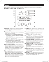
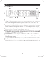
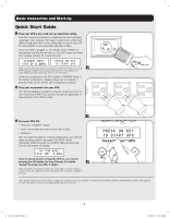
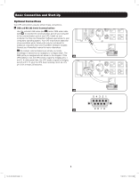
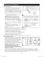
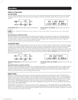
Basic Connection and Start-Up 2 EPO Port Connection This optional feature is only for those applications that require connection to a facility's Emergency Power Off (EPO) circuit. When the UPS is connected to this circuit, it enables emergency shutdown of the UPS's inverter and inhibits transfer to internal bypass. Using the cable provided, connect the EPO port of your UPS (see 2A ) to a user-supplied normally closed or normally open switch according to the circuit diagram (see 2B ). Note: 1. If using a cable other than what is supplied, the cable should not exceed 350 feet or have a resistance of greater than 10 ohms. 2. If a non-latching EPO switch is used, the EPO must be held for a minimum of 1 second. This does not apply to a latching EPO switch. 2A CAUTION: The EPO port is not a phone line surge suppressor; do not connect a phone line to this port. UPS Unit State when asserting EPO with AC line present: 4-5 LEDs Output Fans Serial SNMP USB LCD Screen OFF OFF ON ON ON ON "EMERGENCY POWER OFF" To restart the UPS unit after asserting EPO with AC line present: Option 1: 1. Verify that the EPO assertion has been removed or cleared. 2. Press ON button until unit beeps, then release. 3. Press ON button again and UPS output will turn back on after it completes diagnostics. Option 2: 2B 1. Verify that the EPO assertion has been removed or cleared. 2. Remove AC line power to the UPS unit, wait until the LCD is completely off. 3. Reapply AC line power. Now the UPS will start back up in normal operation mode. UPS Unit State when asserting EPO without AC line power: LEDs Output Fans Serial SNMP USB LCD Screen OFF OFF OFF OFF OFF OFF "EMERGENCY POWER OFF" To restart the UPS unit after asserting EPO without AC line present: 1. Verify that the EPO assertion has been removed or cleared. 2. Reapply AC line power to the UPS unit. Now the UPS will start back up in normal operation mode. 3 External Battery Connection Check the Model Specific Accessories section under Overview for compatible battery packs and maximum quantities for your UPS system. Ensure that your battery pack matches the voltage listed on your UPS battery connector. Adding external batteries will increase recharge time as well as runtime. See the battery pack owner's manual for complete installation and setup instructions. Make sure cables are fully inserted into their connectors. Small sparks may result during battery connection; this is normal. Do not connect or disconnect battery packs when the UPS is running on battery power. IMPORTANT! To calibrate your UPS so that the runtime- remaining LCD and software information screens 3 accurately predict runtime with external battery packs connected, see page 20 for more information if connecting external batteries to this UPS. CAUTION: Do not open or mutilate batteries. Released material is harmful to the skin and eyes. It may be toxic. The following precautions should be observed when working on batteries: Determine if the battery is inadvertently grounded. If inadvertently grounded, remove the source from ground connection. Contact with any part of a grounded battery can result in electrical shock. The likelihood of such a shock can be reduced if grounds are removed during installation and maintenance. (This is applicable to equipment and remote battery supplies that do not have a grounded supply circuit.) 10 13-07-015-9332C3.indb 10 7/26/2013 11:16:14 AM
-
 1
1 -
2
-
3
-
4
-
 5
5 -
 6
6 -
 7
7 -
 8
8 -
 9
9 -
 10
10 -
 11
11 -
 12
12 -
 13
13 -
 14
14 -
 15
15 -
16
-
17
-
18
-
19
-
20
-
21
-
22
-
23
-
24
-
25
-
26
-
27
-
28
-
29
-
30
-
31
-
32
-
33
-
34
-
35
-
36
-
37
-
38
-
39
-
40
-
41
-
42
-
43
-
44
-
45
-
46
-
47
-
48
-
49
-
50
-
51
-
52
-
53
-
54
-
55
-
56
-
57
-
58
-
59
-
60
-
61
-
62
-
63
-
64
-
65
-
66
-
67
-
68
-
69
-
70
-
71
-
72
-
73
-
74
-
75
-
76
-
77
-
78
-
79
-
80
 |
 |
