Tripp Lite SU3000RTXLCD2U Owner's Manual for SU3000RTXLCD2U UPS System 9332C3 - Page 5
Tower Mounting
 |
View all Tripp Lite SU3000RTXLCD2U manuals
Add to My Manuals
Save this manual to your list of manuals |
Page 5 highlights
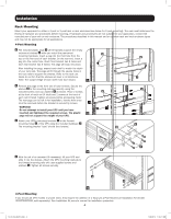
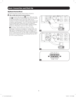
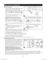
Installation Tower Mounting Your UPS can be mounted in an upright tower position with optional base stands sold separately by Tripp Lite (Model # 2-9USTAND). When mounting the UPS on adjustable base stands, make sure that the control panel is toward the top. Remove the 4 front screws from the front panel and take it off. Pinch the tabs located on the sides of the LCD panel, and then rotate it. Front panel setup should be operated by service personnel only. WARNING! All UPS systems are extremely heavy. Use caution when lifting and mounting. User must properly stabilize the UPS when lifting and mounting. Model UPS Dimensions (HxWxD in.) UPS Dimensions (HxWxD cm.) Operating Altitude: 0 to 3000 m (0 to 10,000 ft.) SU3000RTXLCD2U 3.43 x 17.35 x 25.5 8.71 x 44.07 x 64.77 EXTERNAL BATTERY CONFIGURATION NOTE If external battery packs are to be used with this UPS, install them following the mounting/installation documentation included with each battery pack. External battery pack installation requires the UPS be configured one of two ways: 1. Via the UPS front panel LCD interface 2. Via Tripp Lite's EXTERNAL BATTERY CONFIGURATION software This UPS is factory programmed with discharge curves and charging profiles for two basic external battery pack configurations accessible using the UPS front panel LCD interface. Additional battery pack options using larger or multiple external battery packs are also supported, but require configuration using Tripp Lite's EXTERNAL BATTERY CONFIGURATION software and a serial port connection to the UPS. See page 20 to determine which method applies to your external battery pack configuration. 5 13-07-015-9332C3.indb 5 7/26/2013 11:16:11 AM
-
 1
1 -
 2
2 -
 3
3 -
 4
4 -
 5
5 -
 6
6 -
 7
7 -
 8
8 -
 9
9 -
 10
10 -
 11
11 -
12
-
13
-
14
-
15
-
16
-
17
-
18
-
19
-
20
-
21
-
22
-
23
-
24
-
25
-
26
-
27
-
28
-
29
-
30
-
31
-
32
-
33
-
34
-
35
-
36
-
37
-
38
-
39
-
40
-
41
-
42
-
43
-
44
-
45
-
46
-
47
-
48
-
49
-
50
-
51
-
52
-
53
-
54
-
55
-
56
-
57
-
58
-
59
-
60
-
61
-
62
-
63
-
64
-
65
-
66
-
67
-
68
-
69
-
70
-
71
-
72
-
73
-
74
-
75
-
76
-
77
-
78
-
79
-
80
 |
 |
