Tripp Lite SU3000RTXLCD2U Owner's Manual for SU3000RTXLCD2U UPS System 9332C3 - Page 7
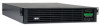
Rear Panel Features
 |
View all Tripp Lite SU3000RTXLCD2U manuals
Add to My Manuals
Save this manual to your list of manuals |
Page 7 highlights
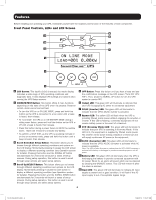
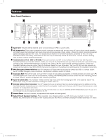
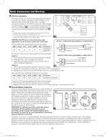
Features Rear Panel Features 3 5 6 8 47 2 9 2 1 1 Input Cord: This permanently attached power cord connects your UPS to a power outlet. 2 AC Receptacles: These output receptacles provide connected equipment with pure sine-wave AC output during normal operation and battery power during blackouts and severe brownouts. Power provided at these outlets is filtered to protect connected equipment against damaging surges and line noise. The receptacles are divided into numbered load banks, as labeled on the unit. Using PowerAlert software and cabling, load banks one and two may be individually turned off and on from a remote location, allowing users to reset or reboot connected equipment. 3 Communications Ports (USB or RS-232): These ports connect your UPS to any workstation or server. Use with Tripp Lite's PowerAlert Software and included cables to enable your computer to automatically save open files and shut down equipment during a blackout. Also use PowerAlert Software to monitor a wide variety of AC line power and UPS operating conditions. Consult your PowerAlert Software manual or contact Tripp Lite Customer Support for more information. The 9-pin RS-232 port also supports drycontact communications. See USB & RS-232 Serial Communications in the Optional Connections section for installation instructions. 4 EPO (Emergency Power Off) Port: Your UPS features an EPO port that may be used to connect the UPS to a contact closure switch to enable emergency inverter shutdown. See Optional Installation section for details. 5 Accessory Slot: Remove the small cover panel from this slot to use optional accessories to remotely monitor and control your UPS. Visit www.tripplite.com to see a full list of accessories, including the SNMPWEBCARD for remote control and UPS monitoring, as well as a wide variety of network management and connectivity products. 6 Input Circuit Breaker: This resettable breaker prevents high input current from damaging the UPS or the attached load. If this breaker trips, verify your UPS load before resetting the breaker switch in. 7 External Battery Pack Connector: Your UPS supports the use of optional Tripp Lite external battery packs for additional runtime. See Model Specific Accessories section under Overview for compatible models and limitations and UPS Setup Overview section under Operation for configuration instructions. Note: External battery pack options require configuration using front panel LCD interface or via Tripp Lite's EXTERNAL BATTERY CONFIGURATION software. See page 20 for more information if you are connecting external batteries to this UPS. 8 Ground Screw: Use this to connect any equipment that requires a chassis ground. 9 Output Circuit Breakers Switches: These resettable circuit breakers protect your UPS from output overload. If one or both breakers trip, remove some of the load on the circuit(s) and allow the UPS to cool before pressing the breaker switch(es) in to reset. 7 13-07-015-9332C3.indb 7 7/26/2013 11:16:12 AM
-
 1
1 -
 2
2 -
 3
3 -
 4
4 -
 5
5 -
 6
6 -
 7
7 -
 8
8 -
 9
9 -
 10
10 -
 11
11 -
 12
12 -
13
-
14
-
15
-
16
-
17
-
18
-
19
-
20
-
21
-
22
-
23
-
24
-
25
-
26
-
27
-
28
-
29
-
30
-
31
-
32
-
33
-
34
-
35
-
36
-
37
-
38
-
39
-
40
-
41
-
42
-
43
-
44
-
45
-
46
-
47
-
48
-
49
-
50
-
51
-
52
-
53
-
54
-
55
-
56
-
57
-
58
-
59
-
60
-
61
-
62
-
63
-
64
-
65
-
66
-
67
-
68
-
69
-
70
-
71
-
72
-
73
-
74
-
75
-
76
-
77
-
78
-
79
-
80
 |
 |
