Alesis Strike MultiPad User Guide - Page 5
Rear Panel, Basic, Operation, Customizing Kits and Sounds, Importing Files from USB - foot pedal
 |
View all Alesis Strike MultiPad manuals
Add to My Manuals
Save this manual to your list of manuals |
Page 5 highlights
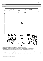
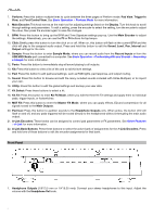
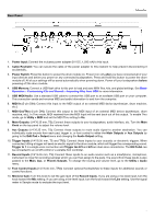
Rear Panel 1. Power Input: Connect the included power adapter (9 V DC, 1,500 mA) to this input. 2. Cable Restraint: You can secure the cable of the power adapter to this restraint to help prevent disconnecting it accidentally. 3. Power Switch: Press this button to power the drum module on. Power it on only after you have connected all of your input devices and before you power on any connected loudspeakers. Press and hold this button to power the drum module off. All of your settings will be saved automatically when powering down. Power off your loudspeakers before powering off the drum module. 4. USB Memory: Connect a USB flash drive to this port to load and save WAV files, kits, and global settings. See Basic Operation > Customizing Kits and Sounds > Importing Files from USB for more information. 5. USB MIDI/Audio: Use a standard USB cable to connect this USB port to an available USB port on your computer. This connection sends and receives MIDI and audio information to and from the computer. 6. MIDI In (5-pin DIN): Connect this input to the MIDI output of an external MIDI device (synthesizer, drum machine, etc.). 7. MIDI Out/Thru (5-pin DIN): Connect this output to the MIDI input of an external MIDI device (synthesizer, drum machine, etc.). In Thru mode, MIDI received from the MIDI Input will be sent back out of this output. To enable Thru mode, go to Utility > MIDI and set the MIDI Thru setting to On. 8. Main Outputs: (1/4"/6.35 mm, TS): Connect these outputs to your loudspeakers, audio interface, etc. Turn the Main Knob on the top panel to adjust the volume level. 9. Aux Outputs (1/4"/6.35 mm, TS): Connect these outputs to route audio signal to another destination. You can individually route sounds from each pad, trigger in, or foot control to either the Main Outputs or Aux Outputs by going to the Edit Pad > Output menu and changing the Audio Output setting. 10. Trigger Inputs (1/4"/6.35 mm, TS and TRS): Connect these inputs to your acoustic or electronic triggers. When connected, hitting a trigger will send an electric signal to the drum module, which will trigger the corresponding sound. Trigger In 1 is a single-zone connection and Trigger Ins 2/3 and 4/5 are dual-zone connections. The HH Pedal can be connected to an on/off control or a variable foot controller. 11. Record Inputs (1/4"/6.35 mm, TS): Connect these inputs to an audio source such as a smartphone, microphone, instrument or mixer for recording samples which you can then assign to the pads. The sound from these inputs is also passed to the Main, Aux, or Phones Outputs. To change the routing and volume level, go to the Utility > Audio menu. 12. Foot Control Inputs (1/4"/6.35 mm, TRS): Connect optional footswitches to these inputs for additional sounds or control functions. 13. Mic/Line Gain: Turn this knob to set the gain level of the Record Inputs. If you are using a mic-level input, turn the knob toward the Mic setting. If you are using a line-level input, turn the knob toward the Line setting. Use the signal meter in Sample mode to evaluate the input level. 5
-
 1
1 -
 2
2 -
 3
3 -
 4
4 -
 5
5 -
 6
6 -
 7
7 -
 8
8 -
 9
9 -
 10
10 -
 11
11 -
12
-
13
-
14
-
15
-
16
-
17
-
18
-
19
-
20
-
21
-
22
-
23
-
24
-
25
-
26
-
27
-
28
-
29
-
30
-
31
 |
 |
