Campbell Scientific CR10 CR10 Measurement and Control - Page 52
Integ.
 |
View all Campbell Scientific CR10 manuals
Add to My Manuals
Save this manual to your list of manuals |
Page 52 highlights
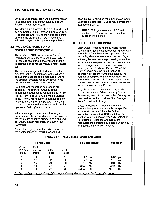
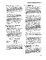
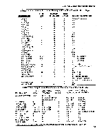
SECTION 3. INSTRUCTION SET BASICS 90, Step Loop lndex, allows the increment step to be changed. See Instructions 87 and 90, Section 12,for more details. possible overranging on the other analog in Voltages greater than 16 volts may damage the CR10. To index an input location (4 digit integer) or set port command (2 digit integer) parameter, C or "-" is pressed after keying the value but before entering the parameter. Two minus signs (-) will be displayed to the right of the parameter. 3.5 VOLTAGE RANGE AND OVERRANGE DETECTION The voltage RANGE code parameter on InpuVOutput lnstructions is used to specify the full scale range of the measurement and the integration period for the measurement (Table 3.s-1). The full scale range selected should be the smallest that will accommodate the full scale output of the sensor being measured. Using the smallest possible range will result in the best resolution for the measurement. Four ditferent integration sequences are possible. The relative immunity of the integration sequences to random noise is: 60 Hz rei. = 50 Hz rei. > 2.72ms integ. > 2721ts integ. The 60 Hz rejection integration rejects noise from 60 Hz AC line power. The 50 Hz rejection is for countries whose electric utilities operate at 50 Hz (Section 13.1). When a voltage input exceeds the range programmed, the value which is stored is set to the maximum negative number and displayed as -99999 in high resolution or -6999 in low resolution. An input voltage greater than +5 volts on one of the analog inputs will result in errors and NOTE: Voltages in excess of 5.5 volts applied to a control port can cause the CR10 to malfunction. 3.6 OUTPUT PROCESSING Most Output Processing Instructions require both an lntermediate Data Processing and a FinalData Processing operation. For example, when the Average Instruction, 71, is initiated, the i ntermediate processi n g operation increments a sample count and adds each new lnput Storage value to a cumulative total residing in lntermediate Storage. When the Output Flag is set, the final processing operation divides the cumulative total by the number of samples to find the average. The average is then stored in finalstorage and the cumulative totaland number of samples are set to zero in Intermediate Storage. Final Storage Area 1 (Sections 1.5, 2.1) is the default destination of data output by Output Processing Instructions. Instruction 80 may be used to direct output to either Final Storage Area2 or to lnput Storage. Output Processing lnstructions requiring intermediate processing sample the specified input location(s) each time the Output lnstruction is executed, NOT each time the location value is updated by an l/O Instruction. For example: Suppose a temperature measurement is initiated by Table 1 which has an execution intervalof 1 second. TABLE 3.5-1. lnput Voltage Ranges and Codes Range Code Slow Fast 2.72ms 250 us 60 Hz Integ. Integ. Reject. 50 Hz Reject. 1112131 2122232 34113422343334 5152535 * Differential measurement. resolution for FullScale Range Resolution* t2.5 mV t7.5 mV x25 mV 1250 mV t2500 mV 0.33 pV 1. pV 3.33 pV 33.3 pV 333. pV measurement is twice value shown. 3-2
-
 1
1 -
2
-
3
-
4
-
5
-
6
-
7
-
8
-
9
-
10
-
11
-
12
-
13
-
14
-
15
-
16
-
17
-
18
-
19
-
20
-
21
-
22
-
23
-
24
-
25
-
26
-
27
-
28
-
29
-
30
-
31
-
32
-
33
-
34
-
35
-
36
-
37
-
38
-
39
-
40
-
41
-
42
-
43
-
44
-
45
-
46
-
 47
47 -
 48
48 -
 49
49 -
 50
50 -
 51
51 -
 52
52 -
 53
53 -
 54
54 -
 55
55 -
 56
56 -
 57
57 -
58
-
59
-
60
-
61
-
62
-
63
-
64
-
65
-
66
-
67
-
68
-
69
-
70
-
71
-
72
-
73
-
74
-
75
-
76
-
77
-
78
-
79
-
80
-
81
-
82
-
83
-
84
-
85
-
86
-
87
-
88
-
89
-
90
-
91
-
92
-
93
-
94
-
95
-
96
-
97
-
98
-
99
-
100
-
101
-
102
-
103
-
104
-
105
-
106
-
107
-
108
-
109
-
110
-
111
-
112
-
113
-
114
-
115
-
116
-
117
-
118
-
119
-
120
-
121
-
122
-
123
-
124
-
125
-
126
-
127
-
128
-
129
-
130
-
131
-
132
-
133
-
134
-
135
-
136
-
137
-
138
-
139
-
140
-
141
-
142
-
143
-
144
-
145
-
146
-
147
-
148
-
149
-
150
-
151
-
152
-
153
-
154
-
155
-
156
-
157
-
158
-
159
-
160
-
161
-
162
-
163
-
164
-
165
-
166
-
167
-
168
-
169
-
170
-
171
-
172
-
173
-
174
-
175
-
176
-
177
-
178
-
179
-
180
-
181
-
182
-
183
-
184
-
185
-
186
-
187
-
188
-
189
-
190
-
191
-
192
-
193
-
194
-
195
-
196
-
197
-
198
-
199
-
200
-
201
-
202
-
203
-
204
-
205
-
206
-
207
-
208
-
209
-
210
-
211
-
212
-
213
-
214
-
215
-
216
-
217
-
218
-
219
-
220
-
221
-
222
-
223
-
224
-
225
-
226
-
227
-
228
-
229
-
230
-
231
-
232
-
233
-
234
-
235
-
236
-
237
-
238
 |
 |
