Canon DR-7080C User Manual - Page 22
Air Vents, USB Connector, DIP Switches, SCSI Connectors, Power Cord Connector
 |
View all Canon DR-7080C manuals
Add to My Manuals
Save this manual to your list of manuals |
Page 22 highlights
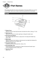
Chapter 1 Getting Ready Rear !2 Air Vents !3 USB Connector Connect a Hi-Speed USB 2.0 compatible USB cable here. (See p. 28.) !4 DIP Switches Configure these switches to specify the SCSI ID or terminator ON or OFF. (See p. 26.) !5 SCSI Connectors Connect a SCSI cable (50-pin half pitch, pin type) here. (See p. 25.) !6 Power Cord Connector Connect the provided power cord here. Important ● Never touch the cables on the left side of the back panel. Disconnection of cables can cause a malfunction of the scanner. ● Take care to ensure that the vents never become blocked. Blocked vents can lead to heat build-up inside the scanner and create the risk of fire. 18
-
 1
1 -
2
-
3
-
4
-
5
-
6
-
7
-
8
-
9
-
10
-
11
-
12
-
13
-
14
-
15
-
16
-
 17
17 -
 18
18 -
 19
19 -
 20
20 -
 21
21 -
 22
22 -
 23
23 -
 24
24 -
 25
25 -
 26
26 -
 27
27 -
28
-
29
-
30
-
31
-
32
-
33
-
34
-
35
-
36
-
37
-
38
-
39
-
40
-
41
-
42
-
43
-
44
-
45
-
46
-
47
-
48
-
49
-
50
-
51
-
52
-
53
-
54
-
55
-
56
-
57
-
58
-
59
-
60
-
61
-
62
-
63
-
64
-
65
-
66
-
67
-
68
-
69
-
70
-
71
-
72
-
73
-
74
-
75
-
76
-
77
-
78
-
79
-
80
-
81
-
82
-
83
-
84
-
85
-
86
-
87
-
88
-
89
-
90
-
91
-
92
-
93
-
94
-
95
-
96
-
97
-
98
-
99
-
100
-
101
-
102
-
103
-
104
-
105
-
106
-
107
-
108
-
109
-
110
-
111
-
112
 |
 |

18
Chapter 1
Getting Ready
Rear
!2
Air Vents
!3
USB Connector
Connect a Hi-Speed USB 2.0 compatible USB cable here. (See p. 28.)
!4
DIP Switches
Configure these switches to specify the SCSI ID or terminator ON or OFF.
(See p. 26.)
!5
SCSI Connectors
Connect a SCSI cable (50-pin half pitch, pin type) here. (See p. 25.)
!6
Power Cord Connector
Connect the provided power cord here.
●
Never touch the cables on the left side of the back panel. Disconnection of cables
can cause a malfunction of the scanner.
●
Take care to ensure that the vents never become blocked. Blocked vents can lead to
heat build-up inside the scanner and create the risk of fire.
Important