Cisco 2970 Hardware Installation Guide - Page 109
RJ-21 Cable Pinouts, Console Port
 |
UPC - 746320852614
View all Cisco 2970 manuals
Add to My Manuals
Save this manual to your list of manuals |
Page 109 highlights
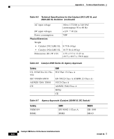
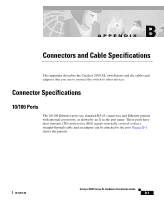
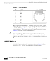
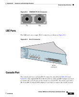
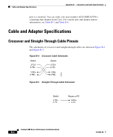
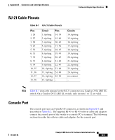
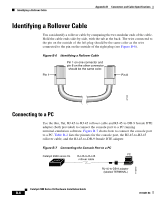
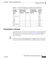
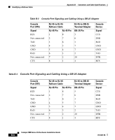
Appendix B Connectors and Cable Specifications Cable and Adapter Specifications RJ-21 Cable Pinouts Table B-1 RJ-21 Cable Pinouts Pins 1, 26 2, 27 3, 28 4, 29 5, 30 6, 31 7, 32 8, 33 9, 34 10, 35 11, 36 12, 37 13, 38 Circuit Pins 1, tip/ring 14, 39 2, tip/ring 15, 40 3, tip/ring 16, 41 4, tip/ring 17, 42 5, tip/ring 18, 43 6, tip/ring 19, 44 7, tip/ring 20, 45 8, tip/ring 21, 46 9, tip/ring 22, 47 10, tip/ring 23, 48 11, tip/ring 24, 49 12, tip/ring 25, 50 13, tip/ring - Circuits 14, tip/ring 15, tip/ring 16, tip/ring 17, tip/ring 18, tip/ring 19, tip/ring 20, tip/ring 21, tip/ring 22, tip/ring 23, tip/ring 24, tip/ring no connect - Note Table B-1 shows the pinouts for the RJ-21 connector on a Catalyst 2924 LRE XL switch. On a Catalyst 2912 LRE XL switch, only circuits 1 to 12 are valid. Console Port The console port uses an 8-pin RJ-45 connector, as shown in Figure B-7 and described in Table B-2. The supplied RJ-45-to-RJ-45 rollover cable and adapters connect the console port of the switch to a console PC or terminal. The following sections describe the rollover cable and adapters for the console port. 78-6461-04 Catalyst 2900 Series XL Hardware Installation Guide B-5
-
 1
1 -
2
-
3
-
4
-
5
-
6
-
7
-
8
-
9
-
10
-
11
-
12
-
13
-
14
-
15
-
16
-
17
-
18
-
19
-
20
-
21
-
22
-
23
-
24
-
25
-
26
-
27
-
28
-
29
-
30
-
31
-
32
-
33
-
34
-
35
-
36
-
37
-
38
-
39
-
40
-
41
-
42
-
43
-
44
-
45
-
46
-
47
-
48
-
49
-
50
-
51
-
52
-
53
-
54
-
55
-
56
-
57
-
58
-
59
-
60
-
61
-
62
-
63
-
64
-
65
-
66
-
67
-
68
-
69
-
70
-
71
-
72
-
73
-
74
-
75
-
76
-
77
-
78
-
79
-
80
-
81
-
82
-
83
-
84
-
85
-
86
-
87
-
88
-
89
-
90
-
91
-
92
-
93
-
94
-
95
-
96
-
97
-
98
-
99
-
100
-
101
-
102
-
103
-
 104
104 -
 105
105 -
 106
106 -
 107
107 -
 108
108 -
 109
109 -
 110
110 -
 111
111 -
 112
112 -
 113
113 -
 114
114 -
115
-
116
-
117
-
118
-
119
-
120
-
121
-
122
-
123
-
124
-
125
-
126
-
127
-
128
-
129
-
130
-
131
-
132
-
133
-
134
-
135
-
136
-
137
-
138
-
139
-
140
-
141
-
142
-
143
-
144
-
145
-
146
-
147
-
148
-
149
-
150
-
151
-
152
-
153
-
154
-
155
-
156
-
157
-
158
-
159
-
160
-
161
-
162
 |
 |
