Cisco 2970 Hardware Installation Guide - Page 75
Positive and Negative Positions on the Switch Rear Panel
 |
UPC - 746320852614
View all Cisco 2970 manuals
Add to My Manuals
Save this manual to your list of manuals |
Page 75 highlights
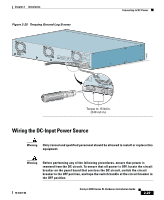
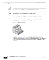
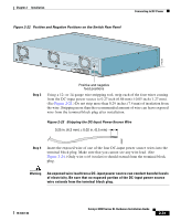
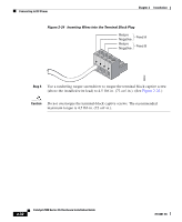
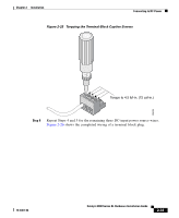
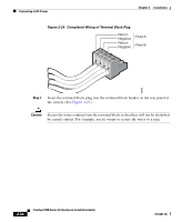
Chapter 2 Installation Figure 2-22 Positive and Negative Positions on the Switch Rear Panel Connecting to DC Power 74078 CONSOLE BERFEOFREERPOCTOWONEMNRAENCUTAINL G DC INPUT ICNUPRURTE: 3N6T:- 72 4-2A A +- B +- Step 3 Positive and negative feed positions Using a 12- or 14-gauge wire-stripping tool, strip each of the four wires coming from the DC-input power source to 0.27 inch (6.86 mm) ± 0.05 inch (1.27 mm). (See Figure 2-23.) Do not strip more than 0.29 inches (7.4 mm) of insulation from the wire. Stripping more than the recommended amount of wire can leave exposed wire from the terminal block plug after installation. Figure 2-23 Stripping the DC-Input Power-Source Wire 0.25 in. (6.3 mm) ± 0.02 in. (0.5 mm) 60531 Step 4 Insert the exposed wire of one of the four DC-input power source wires into the terminal block plug. Make sure that you cannot see any wire lead. (See Figure 2-24.) Only wire with insulation should extend from the terminal block plug. Warning An exposed wire lead from a DC-input power source can conduct harmful levels of electricity. Be sure that no exposed portion of the DC-input power source wire extends from the terminal block plug. 78-6461-04 Catalyst 2900 Series XL Hardware Installation Guide 2-31
-
 1
1 -
2
-
3
-
4
-
5
-
6
-
7
-
8
-
9
-
10
-
11
-
12
-
13
-
14
-
15
-
16
-
17
-
18
-
19
-
20
-
21
-
22
-
23
-
24
-
25
-
26
-
27
-
28
-
29
-
30
-
31
-
32
-
33
-
34
-
35
-
36
-
37
-
38
-
39
-
40
-
41
-
42
-
43
-
44
-
45
-
46
-
47
-
48
-
49
-
50
-
51
-
52
-
53
-
54
-
55
-
56
-
57
-
58
-
59
-
60
-
61
-
62
-
63
-
64
-
65
-
66
-
67
-
68
-
69
-
 70
70 -
 71
71 -
 72
72 -
 73
73 -
 74
74 -
 75
75 -
 76
76 -
 77
77 -
 78
78 -
 79
79 -
 80
80 -
81
-
82
-
83
-
84
-
85
-
86
-
87
-
88
-
89
-
90
-
91
-
92
-
93
-
94
-
95
-
96
-
97
-
98
-
99
-
100
-
101
-
102
-
103
-
104
-
105
-
106
-
107
-
108
-
109
-
110
-
111
-
112
-
113
-
114
-
115
-
116
-
117
-
118
-
119
-
120
-
121
-
122
-
123
-
124
-
125
-
126
-
127
-
128
-
129
-
130
-
131
-
132
-
133
-
134
-
135
-
136
-
137
-
138
-
139
-
140
-
141
-
142
-
143
-
144
-
145
-
146
-
147
-
148
-
149
-
150
-
151
-
152
-
153
-
154
-
155
-
156
-
157
-
158
-
159
-
160
-
161
-
162
 |
 |
