Cisco 2970 Hardware Installation Guide - Page 85
Cisco LRE 48 POTS Splitter PS-1M-LRE-48, refer to the, Switched Telephone Network PSTN.
 |
UPC - 746320852614
View all Cisco 2970 manuals
Add to My Manuals
Save this manual to your list of manuals |
Page 85 highlights
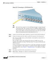
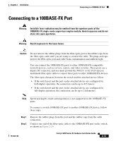
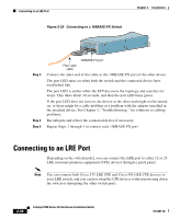
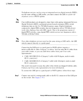
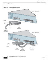
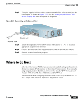
Chapter 2 Installation Connecting to an LRE Port Step 2 Referring to Figure 2-30, secure the cable to the switch: • For a 90-degree connector, see the top of Figure 2-30. • For a 12-degree connector, see the bottom Figure 2-30. Note The cable tie is not included with the connector and cable assembly. Step 3 Connect the other end of the cable to the patch panel or POTS splitter. Each LRE port status LED turns on when it establishes a link with a Cisco LRE CPE. For more information about the LRE link between the switch LRE port and the CPE, as well as information about the configuration and management of CPE devices, refer to the Catalyst 2900 Series XL and Catalyst 3500 Series XL Software Configuration Guide. For more information about the Cisco LRE CPE devices, refer to the Cisco LRE CPE Hardware Installation Guide. If telephone services, such as voice or ISDN, use the same cabling as LRE traffic, the LRE port must be connected to the patch panel through a basic telephone service, also known as plain old telephone service (POTS) splitter. The splitter routes LRE data (high-frequency) and voice (low-frequency) traffic from the telephone line to the switch and private branch exchange (PBX) switch or Public Switched Telephone Network (PSTN). If the other telephone services are connected through a PBX switch, a Cisco LRE 48 POTS Splitter can be used. The PBX routes voice traffic to private telephone networks and the PSTN. For more information about the Cisco LRE 48 POTS Splitter (PS-1M-LRE-48), refer to the Installation Notes for the Cisco LRE 48 POTS Splitter. If the installation does not have a PBX, a homologated POTS splitter is required to directly connect to the PSTN. For more information about homologated POTS splitters, contact your Cisco sales representative. Note If a connection to a telephone network is not required at all, a splitter is not needed, and the switch can connect directly to the patch panel. 78-6461-04 Catalyst 2900 Series XL Hardware Installation Guide 2-41
-
 1
1 -
2
-
3
-
4
-
5
-
6
-
7
-
8
-
9
-
10
-
11
-
12
-
13
-
14
-
15
-
16
-
17
-
18
-
19
-
20
-
21
-
22
-
23
-
24
-
25
-
26
-
27
-
28
-
29
-
30
-
31
-
32
-
33
-
34
-
35
-
36
-
37
-
38
-
39
-
40
-
41
-
42
-
43
-
44
-
45
-
46
-
47
-
48
-
49
-
50
-
51
-
52
-
53
-
54
-
55
-
56
-
57
-
58
-
59
-
60
-
61
-
62
-
63
-
64
-
65
-
66
-
67
-
68
-
69
-
70
-
71
-
72
-
73
-
74
-
75
-
76
-
77
-
78
-
79
-
 80
80 -
 81
81 -
 82
82 -
 83
83 -
 84
84 -
 85
85 -
 86
86 -
 87
87 -
 88
88 -
 89
89 -
 90
90 -
91
-
92
-
93
-
94
-
95
-
96
-
97
-
98
-
99
-
100
-
101
-
102
-
103
-
104
-
105
-
106
-
107
-
108
-
109
-
110
-
111
-
112
-
113
-
114
-
115
-
116
-
117
-
118
-
119
-
120
-
121
-
122
-
123
-
124
-
125
-
126
-
127
-
128
-
129
-
130
-
131
-
132
-
133
-
134
-
135
-
136
-
137
-
138
-
139
-
140
-
141
-
142
-
143
-
144
-
145
-
146
-
147
-
148
-
149
-
150
-
151
-
152
-
153
-
154
-
155
-
156
-
157
-
158
-
159
-
160
-
161
-
162
 |
 |