Cisco 2970 Hardware Installation Guide - Page 6
Attaching the Brackets to a Catalyst 2912 XL, 2924C XL, 2912MF XL - switch
 |
UPC - 746320852614
View all Cisco 2970 manuals
Add to My Manuals
Save this manual to your list of manuals |
Page 6 highlights
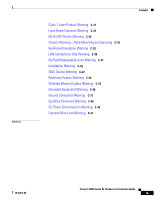
Contents Module Slots 1-8 LEDs 1-9 System LED 1-12 RPS LED 1-13 Port LEDs and Modes 1-14 Module Slot LEDs 1-19 Rear-Panel Description 1-19 Power Connectors 1-21 Internal Power Supply Connector 1-21 DC Power Connector 1-21 Cisco RPS Connector 1-22 Console Port 1-23 2 C H A P T E R Installation 2-1 Preparing for Installation 2-1 Warnings 2-1 EMC Regulatory Statements 2-4 U.S.A. 2-4 Taiwan 2-4 Japan 2-5 Korea 2-5 Hungary 2-6 Installation Guidelines 2-6 Verifying Package Contents 2-7 Installing the Switch on a Table or Shelf 2-9 Installing the Switch in a Rack 2-9 Removing Screws from the Switch 2-11 Attaching the Brackets to a Catalyst 2912 XL, 2924C XL, 2924 XL, 2912MF XL, 2924M XL, or 2924M XL DC Switch 2-11 Attaching the Brackets to a Catalyst 2912 LRE XL or 2924 LRE XL Switch 2-16 Catalyst 2900 Series XL Hardware Installation Guide vi 78-6461-04
-
 1
1 -
 2
2 -
 3
3 -
 4
4 -
 5
5 -
 6
6 -
 7
7 -
 8
8 -
 9
9 -
 10
10 -
 11
11 -
 12
12 -
13
-
14
-
15
-
16
-
17
-
18
-
19
-
20
-
21
-
22
-
23
-
24
-
25
-
26
-
27
-
28
-
29
-
30
-
31
-
32
-
33
-
34
-
35
-
36
-
37
-
38
-
39
-
40
-
41
-
42
-
43
-
44
-
45
-
46
-
47
-
48
-
49
-
50
-
51
-
52
-
53
-
54
-
55
-
56
-
57
-
58
-
59
-
60
-
61
-
62
-
63
-
64
-
65
-
66
-
67
-
68
-
69
-
70
-
71
-
72
-
73
-
74
-
75
-
76
-
77
-
78
-
79
-
80
-
81
-
82
-
83
-
84
-
85
-
86
-
87
-
88
-
89
-
90
-
91
-
92
-
93
-
94
-
95
-
96
-
97
-
98
-
99
-
100
-
101
-
102
-
103
-
104
-
105
-
106
-
107
-
108
-
109
-
110
-
111
-
112
-
113
-
114
-
115
-
116
-
117
-
118
-
119
-
120
-
121
-
122
-
123
-
124
-
125
-
126
-
127
-
128
-
129
-
130
-
131
-
132
-
133
-
134
-
135
-
136
-
137
-
138
-
139
-
140
-
141
-
142
-
143
-
144
-
145
-
146
-
147
-
148
-
149
-
150
-
151
-
152
-
153
-
154
-
155
-
156
-
157
-
158
-
159
-
160
-
161
-
162
 |
 |