Cisco 2970 Hardware Installation Guide - Page 87
Where to Go Next - switch ios
 |
UPC - 746320852614
View all Cisco 2970 manuals
Add to My Manuals
Save this manual to your list of manuals |
Page 87 highlights
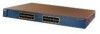
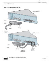
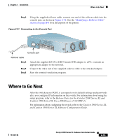
Chapter 2 Installation Where to Go Next Step 3 Using the supplied rollover cable, connect one end of the rollover cable into the console port, as shown in Figure 2-31. See the "Identifying a Rollover Cable" section on page B-6 for a description of the pinout. Figure 2-31 Connecting to the Console Port CONSOLE +D5SCVPIENPC@POIUFW2TI4EESADR,[email protected] 47308 Console port Rollover cable Step 4 Step 5 Step 6 Attach the supplied RJ-45-to-DB-9 female DTE adapter to a PC, or attach an appropriate adapter to the terminal. Connect the other end of the supplied rollover cable to the attached adapter. Start the terminal-emulation program. Where to Go Next After the switch passes POST, it can operate on its default settings and passwords after you configure IP information on the switch. For information about using the setup program, refer to the Release Notes for the Catalyst 2900 Series XL and Catalyst 3500 Series XL Cisco IOS Release 12.0(5)WC(1). For information about configuring the switch, refer to the Catalyst 2900 Series XL and Catalyst 3500 Series XL Software Configuration Guide. 78-6461-04 Catalyst 2900 Series XL Hardware Installation Guide 2-43
-
 1
1 -
2
-
3
-
4
-
5
-
6
-
7
-
8
-
9
-
10
-
11
-
12
-
13
-
14
-
15
-
16
-
17
-
18
-
19
-
20
-
21
-
22
-
23
-
24
-
25
-
26
-
27
-
28
-
29
-
30
-
31
-
32
-
33
-
34
-
35
-
36
-
37
-
38
-
39
-
40
-
41
-
42
-
43
-
44
-
45
-
46
-
47
-
48
-
49
-
50
-
51
-
52
-
53
-
54
-
55
-
56
-
57
-
58
-
59
-
60
-
61
-
62
-
63
-
64
-
65
-
66
-
67
-
68
-
69
-
70
-
71
-
72
-
73
-
74
-
75
-
76
-
77
-
78
-
79
-
80
-
81
-
 82
82 -
 83
83 -
 84
84 -
 85
85 -
 86
86 -
 87
87 -
 88
88 -
 89
89 -
 90
90 -
 91
91 -
 92
92 -
93
-
94
-
95
-
96
-
97
-
98
-
99
-
100
-
101
-
102
-
103
-
104
-
105
-
106
-
107
-
108
-
109
-
110
-
111
-
112
-
113
-
114
-
115
-
116
-
117
-
118
-
119
-
120
-
121
-
122
-
123
-
124
-
125
-
126
-
127
-
128
-
129
-
130
-
131
-
132
-
133
-
134
-
135
-
136
-
137
-
138
-
139
-
140
-
141
-
142
-
143
-
144
-
145
-
146
-
147
-
148
-
149
-
150
-
151
-
152
-
153
-
154
-
155
-
156
-
157
-
158
-
159
-
160
-
161
-
162
 |
 |