Cisco 2970 Hardware Installation Guide - Page 80
Connecting to a 10/100 Switch Port
 |
UPC - 746320852614
View all Cisco 2970 manuals
Add to My Manuals
Save this manual to your list of manuals |
Page 80 highlights
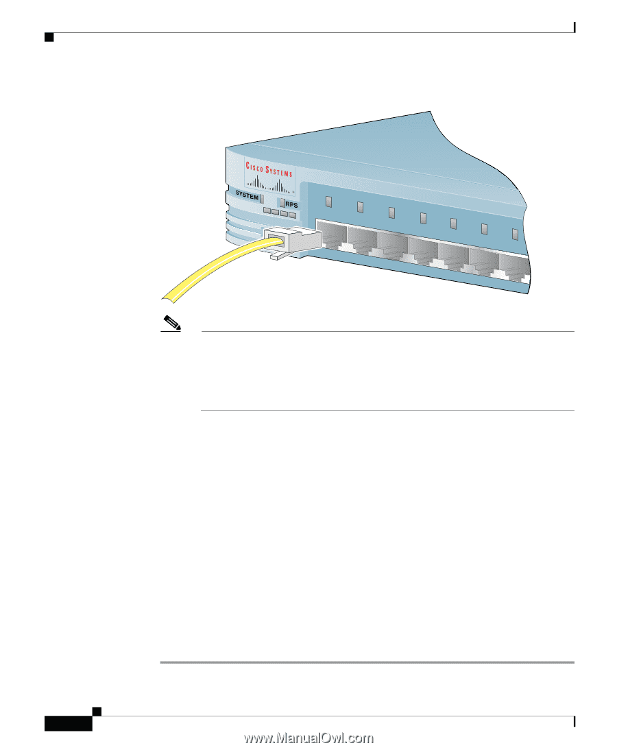
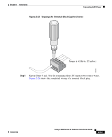
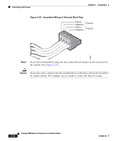
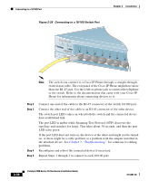
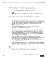
Connecting to a 10/100 Port Figure 2-28 Connecting to a 10/100 Switch Port Chapter 2 Installation MODE 1X 2X 3X 4X 5X 6X 7X 47291 Note The switch can connect to a Cisco IP Phone through a straight-through, twisted-pair cable. The rear panel of the Cisco IP Phone might have more than one RJ-45 jack. Use the LAN-to-phone jack to connect the telephone to the switch. Refer to the documentation that came with your Cisco IP Phone for information about connecting devices to it. Step 2 Step 3 Step 4 Step 5 Connect one end of the cable to the RJ-45 connector of the switch 10/100 port. Connect the other end of the cable to an RJ-45 connector of the other device. The switch port LED comes on when both the switch and the connected device have established link. The port LED is amber while Spanning Tree Protocol (STP) discovers the topology and searches for loops. This takes about 30 seconds, and then the port LED turns green. If the port LED does not turn on, the device at the other end might not be turned on, or there might be a cable problem or a problem with the adapter installed in the attached device. See Chapter 3, "Troubleshooting," for solutions to cabling problems. Reconfigure and reboot the connected device if necessary. Repeat Steps 1 through 3 to connect to each 10/100 port. 2-36 Catalyst 2900 Series XL Hardware Installation Guide 78-6461-04
-
 1
1 -
2
-
3
-
4
-
5
-
6
-
7
-
8
-
9
-
10
-
11
-
12
-
13
-
14
-
15
-
16
-
17
-
18
-
19
-
20
-
21
-
22
-
23
-
24
-
25
-
26
-
27
-
28
-
29
-
30
-
31
-
32
-
33
-
34
-
35
-
36
-
37
-
38
-
39
-
40
-
41
-
42
-
43
-
44
-
45
-
46
-
47
-
48
-
49
-
50
-
51
-
52
-
53
-
54
-
55
-
56
-
57
-
58
-
59
-
60
-
61
-
62
-
63
-
64
-
65
-
66
-
67
-
68
-
69
-
70
-
71
-
72
-
73
-
74
-
 75
75 -
 76
76 -
 77
77 -
 78
78 -
 79
79 -
 80
80 -
 81
81 -
 82
82 -
 83
83 -
 84
84 -
 85
85 -
86
-
87
-
88
-
89
-
90
-
91
-
92
-
93
-
94
-
95
-
96
-
97
-
98
-
99
-
100
-
101
-
102
-
103
-
104
-
105
-
106
-
107
-
108
-
109
-
110
-
111
-
112
-
113
-
114
-
115
-
116
-
117
-
118
-
119
-
120
-
121
-
122
-
123
-
124
-
125
-
126
-
127
-
128
-
129
-
130
-
131
-
132
-
133
-
134
-
135
-
136
-
137
-
138
-
139
-
140
-
141
-
142
-
143
-
144
-
145
-
146
-
147
-
148
-
149
-
150
-
151
-
152
-
153
-
154
-
155
-
156
-
157
-
158
-
159
-
160
-
161
-
162
 |
 |