Cisco 2970 Hardware Installation Guide - Page 68
Powering On the Switch and Running POST
 |
UPC - 746320852614
View all Cisco 2970 manuals
Add to My Manuals
Save this manual to your list of manuals |
Page 68 highlights
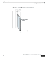
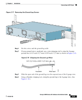
SERIES 16x 17x 18x 19x 20x 21x 22x 23x 24x Powering On the Switch and Running POST Figure 2-16 Mounting a Modular Switch to a Wall Vertical wall stud User-supplied screws User-supplied screws SERIES 10BaseT/100BaseTX 12x 13x 14x 15x 16x 17x 18x 19x 20x 21x 22x 23x 24x Chapter 2 Installation 11x 15x 10x 14x 9x 13x 8x 10BaseT/100BaseTX 12x 7x 6x 11x 5x 10x 4x 9x 3x 8x 2x 7x 1x 6x MODE 5x 4x 3x 2x 1x MODE 47306 Vertical wall-mount Parallel wall-mount After the switch is mounted on the wall, power the switch as described in "Powering On the Switch and Running POST" section on page 2-24. Powering On the Switch and Running POST To power on the switch after you install it, follow these steps: Step 1 Connect one end of the AC power cord to the AC power connector on the switch. Step 2 Connect the other end of the power cord to an AC power outlet. 2-24 As the switch powers on, it begins POST, a series of eight tests that run automatically to ensure that the switch functions properly. When the switch begins POST, the port LEDs turn amber for 2 seconds, and then they turn green. Catalyst 2900 Series XL Hardware Installation Guide 78-6461-04
-
 1
1 -
2
-
3
-
4
-
5
-
6
-
7
-
8
-
9
-
10
-
11
-
12
-
13
-
14
-
15
-
16
-
17
-
18
-
19
-
20
-
21
-
22
-
23
-
24
-
25
-
26
-
27
-
28
-
29
-
30
-
31
-
32
-
33
-
34
-
35
-
36
-
37
-
38
-
39
-
40
-
41
-
42
-
43
-
44
-
45
-
46
-
47
-
48
-
49
-
50
-
51
-
52
-
53
-
54
-
55
-
56
-
57
-
58
-
59
-
60
-
61
-
62
-
 63
63 -
 64
64 -
 65
65 -
 66
66 -
 67
67 -
 68
68 -
 69
69 -
 70
70 -
 71
71 -
 72
72 -
 73
73 -
74
-
75
-
76
-
77
-
78
-
79
-
80
-
81
-
82
-
83
-
84
-
85
-
86
-
87
-
88
-
89
-
90
-
91
-
92
-
93
-
94
-
95
-
96
-
97
-
98
-
99
-
100
-
101
-
102
-
103
-
104
-
105
-
106
-
107
-
108
-
109
-
110
-
111
-
112
-
113
-
114
-
115
-
116
-
117
-
118
-
119
-
120
-
121
-
122
-
123
-
124
-
125
-
126
-
127
-
128
-
129
-
130
-
131
-
132
-
133
-
134
-
135
-
136
-
137
-
138
-
139
-
140
-
141
-
142
-
143
-
144
-
145
-
146
-
147
-
148
-
149
-
150
-
151
-
152
-
153
-
154
-
155
-
156
-
157
-
158
-
159
-
160
-
161
-
162
 |
 |
