Cisco 2970 Hardware Installation Guide - Page 41
Power Connectors, Internal Power Supply Connector, DC Power Connector
 |
UPC - 746320852614
View all Cisco 2970 manuals
Add to My Manuals
Save this manual to your list of manuals |
Page 41 highlights
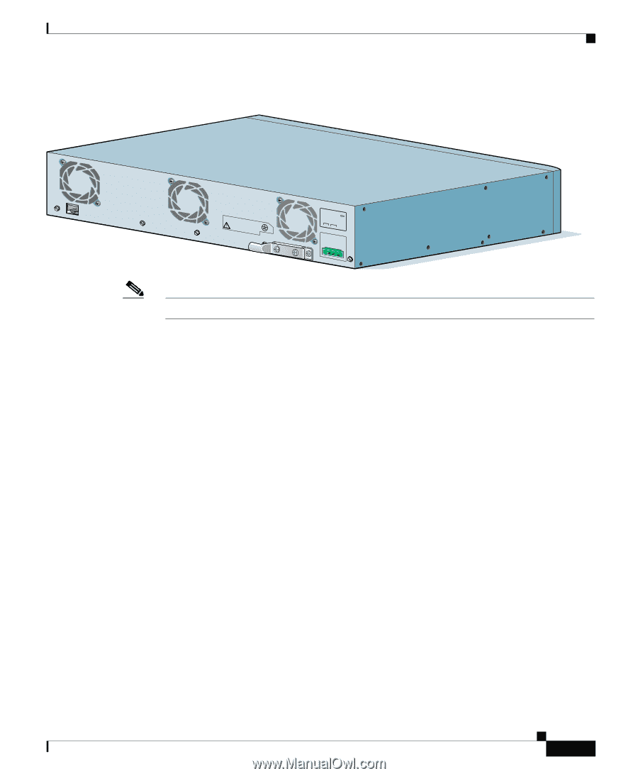
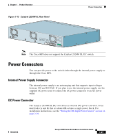
Chapter 1 Product Overview Figure 1-13 Catalyst 2924M XL Rear Panel Power Connectors 74070 CONSOLE BERFEOFREERPOCTOWONEMNRAENCUTAINL G DC INPUT ICNUPRURTE: 3N6T:- 72 4-2A A +- B +- Note The Cisco RPS does not support the Catalyst 2924M XL DC switch. Power Connectors You can provide power to the switch either through the internal power supply or through the Cisco RPS. Internal Power Supply Connector The internal power supply is an autoranging unit that supports input voltages between 100 and 240 VAC. If you plan to use the internal power supply, use the supplied AC power cord to connect the AC power connector to an AC power outlet. DC Power Connector The Catalyst 2924M XL DC switch has an internal DC-power converter. It has dual feeds (A and B) that are diode-OR-ed into a single power block. For installation instructions, see the "Wiring the DC-Input Power Source" section on page 2-29. 78-6461-04 Catalyst 2900 Series XL Hardware Installation Guide 1-21
-
 1
1 -
2
-
3
-
4
-
5
-
6
-
7
-
8
-
9
-
10
-
11
-
12
-
13
-
14
-
15
-
16
-
17
-
18
-
19
-
20
-
21
-
22
-
23
-
24
-
25
-
26
-
27
-
28
-
29
-
30
-
31
-
32
-
33
-
34
-
35
-
 36
36 -
 37
37 -
 38
38 -
 39
39 -
 40
40 -
 41
41 -
 42
42 -
 43
43 -
 44
44 -
 45
45 -
 46
46 -
47
-
48
-
49
-
50
-
51
-
52
-
53
-
54
-
55
-
56
-
57
-
58
-
59
-
60
-
61
-
62
-
63
-
64
-
65
-
66
-
67
-
68
-
69
-
70
-
71
-
72
-
73
-
74
-
75
-
76
-
77
-
78
-
79
-
80
-
81
-
82
-
83
-
84
-
85
-
86
-
87
-
88
-
89
-
90
-
91
-
92
-
93
-
94
-
95
-
96
-
97
-
98
-
99
-
100
-
101
-
102
-
103
-
104
-
105
-
106
-
107
-
108
-
109
-
110
-
111
-
112
-
113
-
114
-
115
-
116
-
117
-
118
-
119
-
120
-
121
-
122
-
123
-
124
-
125
-
126
-
127
-
128
-
129
-
130
-
131
-
132
-
133
-
134
-
135
-
136
-
137
-
138
-
139
-
140
-
141
-
142
-
143
-
144
-
145
-
146
-
147
-
148
-
149
-
150
-
151
-
152
-
153
-
154
-
155
-
156
-
157
-
158
-
159
-
160
-
161
-
162
 |
 |