Cisco 2970 Hardware Installation Guide - Page 70
Grounding the Switch
 |
UPC - 746320852614
View all Cisco 2970 manuals
Add to My Manuals
Save this manual to your list of manuals |
Page 70 highlights
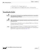
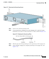
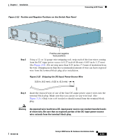
Connecting to DC Power Chapter 2 Installation • Four leads of 12- or 14-gauge copper wire • Wire-stripping tool(s) for stripping both 6- and 12- or 14-gauge wires Grounding the Switch Warning This equipment is intended to be grounded. Ensure that the host is connected to earth ground during normal use. Warning When installing the unit, the ground connection must always be made first and disconnected last. Follow these steps to ground the switch to earth ground. Make sure to follow any grounding requirements at your site. Step 1 Use a standard Phillips screwdriver or a ratcheting torque screwdriver with a Phillips head to remove the two number-10-16 ground-lug screws and the ground lug from the rear panel of the switch. (See Figure 2-17. 2-26 Catalyst 2900 Series XL Hardware Installation Guide 78-6461-04
-
 1
1 -
2
-
3
-
4
-
5
-
6
-
7
-
8
-
9
-
10
-
11
-
12
-
13
-
14
-
15
-
16
-
17
-
18
-
19
-
20
-
21
-
22
-
23
-
24
-
25
-
26
-
27
-
28
-
29
-
30
-
31
-
32
-
33
-
34
-
35
-
36
-
37
-
38
-
39
-
40
-
41
-
42
-
43
-
44
-
45
-
46
-
47
-
48
-
49
-
50
-
51
-
52
-
53
-
54
-
55
-
56
-
57
-
58
-
59
-
60
-
61
-
62
-
63
-
64
-
 65
65 -
 66
66 -
 67
67 -
 68
68 -
 69
69 -
 70
70 -
 71
71 -
 72
72 -
 73
73 -
 74
74 -
 75
75 -
76
-
77
-
78
-
79
-
80
-
81
-
82
-
83
-
84
-
85
-
86
-
87
-
88
-
89
-
90
-
91
-
92
-
93
-
94
-
95
-
96
-
97
-
98
-
99
-
100
-
101
-
102
-
103
-
104
-
105
-
106
-
107
-
108
-
109
-
110
-
111
-
112
-
113
-
114
-
115
-
116
-
117
-
118
-
119
-
120
-
121
-
122
-
123
-
124
-
125
-
126
-
127
-
128
-
129
-
130
-
131
-
132
-
133
-
134
-
135
-
136
-
137
-
138
-
139
-
140
-
141
-
142
-
143
-
144
-
145
-
146
-
147
-
148
-
149
-
150
-
151
-
152
-
153
-
154
-
155
-
156
-
157
-
158
-
159
-
160
-
161
-
162
 |
 |
