Cisco 2970 Hardware Installation Guide - Page 63
Attaching the Optional Cable Guide
 |
UPC - 746320852614
View all Cisco 2970 manuals
Add to My Manuals
Save this manual to your list of manuals |
Page 63 highlights
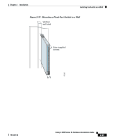
Chapter 2 Installation Figure 2-11 Mounting the Switch in a Rack Installing the Switch in a Rack MODE 1X 2X 3X 4X 5X 6X 7X 8X 9X 10X 10BaseT/100Ba1s0e0TBXaseFX 11X 12X 13X 14X 16X 17X 18X 19X 20X 21X Catalyst 2900 SERIES XL 22X 23X 24X Phillips machine screws 47301 12 MODE 1X 2X 3X Catalyst 2900 SERIES XL 4X 5X 6X 7X 8X 9X 100BaseFX 10X 11X 12X 13X 14X 15X 16X 17X 18X 19X 20X 21X 22X 23X 24X Phillips machine screws After the switch is mounted in the rack, power the switch as described in "Powering On the Switch and Running POST" section on page 2-24. Attaching the Optional Cable Guide We recommend attaching the cable guide to prevent the cables from obscuring the front panel of the switch and the other devices installed in the rack. If the switch is in a 19-, 23-, or 24-inch rack, use the supplied black screw as shown in Figure 2-12 to attach the cable guide to the left or right bracket. The cable guide for the modular switches requires two screws. 78-6461-04 Catalyst 2900 Series XL Hardware Installation Guide 2-19
-
 1
1 -
2
-
3
-
4
-
5
-
6
-
7
-
8
-
9
-
10
-
11
-
12
-
13
-
14
-
15
-
16
-
17
-
18
-
19
-
20
-
21
-
22
-
23
-
24
-
25
-
26
-
27
-
28
-
29
-
30
-
31
-
32
-
33
-
34
-
35
-
36
-
37
-
38
-
39
-
40
-
41
-
42
-
43
-
44
-
45
-
46
-
47
-
48
-
49
-
50
-
51
-
52
-
53
-
54
-
55
-
56
-
57
-
 58
58 -
 59
59 -
 60
60 -
 61
61 -
 62
62 -
 63
63 -
 64
64 -
 65
65 -
 66
66 -
 67
67 -
 68
68 -
69
-
70
-
71
-
72
-
73
-
74
-
75
-
76
-
77
-
78
-
79
-
80
-
81
-
82
-
83
-
84
-
85
-
86
-
87
-
88
-
89
-
90
-
91
-
92
-
93
-
94
-
95
-
96
-
97
-
98
-
99
-
100
-
101
-
102
-
103
-
104
-
105
-
106
-
107
-
108
-
109
-
110
-
111
-
112
-
113
-
114
-
115
-
116
-
117
-
118
-
119
-
120
-
121
-
122
-
123
-
124
-
125
-
126
-
127
-
128
-
129
-
130
-
131
-
132
-
133
-
134
-
135
-
136
-
137
-
138
-
139
-
140
-
141
-
142
-
143
-
144
-
145
-
146
-
147
-
148
-
149
-
150
-
151
-
152
-
153
-
154
-
155
-
156
-
157
-
158
-
159
-
160
-
161
-
162
 |
 |
